The basic concept is that in a dual-supply circuit, "ground" is located halfway between the positive and negative supply voltages. Therefore, all that is required of us is that we arrive at a stabilized voltage that is exactly midway between V+ and V-, and we're ready.
Sadly, conventional voltage regulators seem to be ineffective for the purpose. These can just source current; they cannot sink it.
However, depending on which half of the load is drawing more current at any particular instant, the ground connection in a dual supply may need to source or sink current.
Block Diagram
The concept underlying our unique, function-specific two-way voltage regulator is depicted in Figure 1 block diagram below.
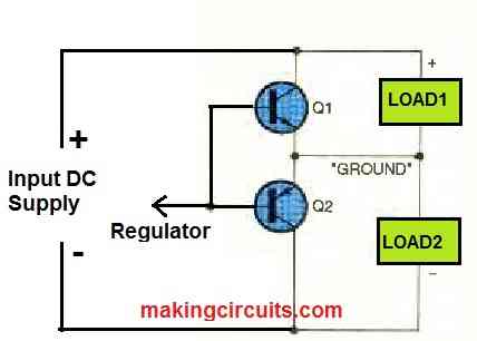
If the currents drawn by loads 1 and 2 are exactly identical, then the voltage between them is already midway between V+ and V-, eliminating the need for any action from the regulator.
Both Q1 and Q2 will conduct extra current to compensate for the difference if the currents consumed by the two loads are dissimilar. In this manner, the ground voltage is maintained exactly midway between the positive and negative rails.
Complete Dual Power Supply Circuit using IC 741
The complete dual power supply circuit is shown in Figure 2 using 2N3055 transistors as the driver transistor.
It divides the input voltage in half thanks to R1 and R2. Op-amp U1 replicates that voltage at the output side labelled "ground" by allowing Q1 or Q2 to conduct to the extent required.
When the load abruptly fluctuates, the output voltage is held constant by capacitors C1 and C2. In order to safeguard the circuit's input from reversed polarity, diode D1 is included. It does this by bursting the main power supply's fuse.
If your power source does not have a fuse, connect D1 in series with the circuit (example, in the positive input line and pointing toward R1). This will ensure the same safety with just relatively low regulation and voltage output.
Aficionados may argue that the output of U1 must pass a practical "dead zone" created by the turn-on voltages of Q1 and Q2 being 1.2 volts apart in order to cope with an imbalanced load.
Although it is theoretically feasible to bias Q1 and Q2 to remove the dead zone, U1 can swiftly cross the dead zone in practice. In any case, C1 and C2 ensure that alterations to the load balance won't occur immediately.
In prolonged testing, this circuit provided good regulation driving "sloppy" loads including buzzers and strobe light bulbs in addition to op-amp circuits.
How to Use
As previously noted, you may use this splitter circuit with power sources that have constant or variable voltage ranges between 8 and 30 volts. Check the isolation of your power supply. To put it another way, neither V+ nor V- should be coupled to the ground or power line ground of the metal enclosure.
What current capacity does the splitter have? It's a challenging question. Keep in mind that the splitter does nothing at all when Loads 1 and 2 are equal.
That's often the case for the majority of op-amp circuits. Generally speaking, this splitter can operate with a 30-volt input while handling a differential of at least 250 mA between the two sides of the load.
Both Q1 and Q2 will become extremely heated as a result of dissipating approximately 4 watts to do that.
Adding a heat sink will help if, during actual operation, the transistors get too hot to touch comfortably. This splitter is capable of handling several amps when equipped with the appropriate transistors and a sufficient heat sink.
This circuit will not work. the base and emitter of q1 and q2 are shorted out.
Yes, there’s a mistake in the 741 circuit. The emitters of the BJts must be disconnected from pin#6 of the IC.