This article teaches us methods to use a single CMOS gate to construct basic oscillator circuits, such as the Hartley and Pierce oscillators. Despite using the fewest possible components, these oscillators are capable of producing incredibly steady and dependable frequency outputs.
The Pierce Oscillator
As seen in the accompanying image, a pierce oscillator circuit designed around a crystal oscillator architecture may be readily created with just one CMOS gate.
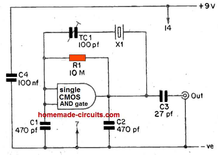
So like you've got this single CMOS inverter gate that's all set up with this R1 to act like a linear amplifier. And there's a crystal hanging out between the input and output of the pierce circuit through this trimmer capacitor TC1.
Now this whole circuit idea is made to work with the crystal's series resonant frequency. And just so you know, we' are not using any positive feedback between the output and input here. Thats because the CMOS amplifier's input and output are doing their thing in antiphase mode.
With series resonance in the mix, it might seem like the crystal is giving some negative feedback to the amplifier. But that might not really be what's happening. See C1 and C2 are making this capacitive center tap thing around the crystal and that center tap is, like, grounded.
So the crystal's acting like a transformer of sorts, working in series resonance mode using its two connections in antiphase. Because of that we might find a 180-degree phase shift happening, thanks to both the amplifier and the crystal which gives us positive feedback too.
TC1 is there to tweak the circuit's oscillation frequency so it matches the crystal's frequency but if you do not need it, you can totally ditch it. Just take out TC1 and hook the crystal straight across R1.
Those capacitors C1 and C2, are hanging out with values of 470 pF each in this pierce circuit design. With these values, the circuit should oscillate without any hiccups across a bunch of different frequencies.
If the frequency is only a few MHz you might wanna make C1 and C2 a bit smaller to keep the oscillation going strong. On the flip side if the frequency is lower than a few 100 kHz, you can go for slightly bigger C1 and C2 values.
The diagram shows an AND CMOS gate but you could also use a buffer CMOS gate like the one from the IC 4050.
And if you're into using an FET, one cool thing about the Pierce crystal oscillator circuit is that you dont have to mess with any tuning adjustments. The figure shows how to build up a Pierce oscillator circuit using a single 2N3823 (or 2N3821, 2N3822) field-effect transistor.
Pierce Oscillator Circuit using Just One FET
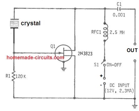
In this setup, the quartz crystal or XTAL is basically getting a workout, driven between the FET's drain/output and gate/input stages.
Now this 2.5-mh RF choke RFC1, it' is usually not there to tune the circuit or anything fancy. It' is mostly just keeping the RF energy from messing with the DC supply. The moment you flip switch S1 ON, the circuit just starts oscillating.
For getting the output signal out, we' are using capacitive output coupling with capacitor C1. This makes sure that the external load impedance stays high enough so it does not overload the circuit and kill the oscillations.
When this Pierce oscillator circuit is operating at the crystal frequency, it' is using about 2.3 ma of current from the 12 V DC supply.
And get this, without any load attached the RF output signal amplitude is around 6.2v RMS. Just so you know, this is all happening at a 7 MHz frequency.
Now the Pierce circuit is made to oscillate at the fundamental frequency of the crystal. So if you've got a harmonic-type crystal, it's going to oscillate at its main frequency, not necessarily the harmonic frequency it's supposed to be at. Also just a heads up, the Pierce oscillator needs a super active crystal to work its magic.
Another Single FET Pierce Oscillator Circuit
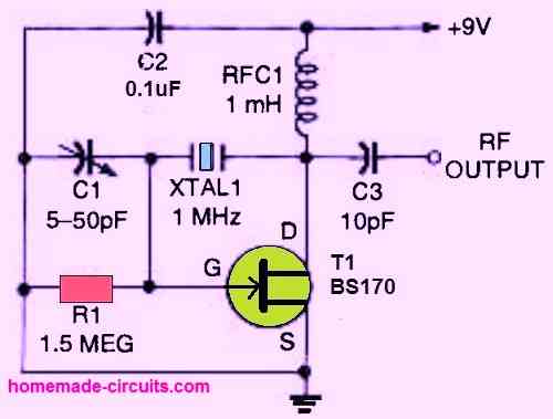
The illustrations above shows a different simple Pierce crystal-controlled oscillator circuit. For transmitter alignment, this circuit could possibly be used as a marker generator.
One FET (field-effect transistor) BS170 is the active component that produces adequate gain for the circuit to oscillate. Through the crystal, the FET's drain (d) provides feedback to the input gate. The trimmer capacitor C1 fine-tunes the oscillator.
Leave a Reply