So in this article, we are discussing one super simple kind of circuit which is actually a wireless speaker system. We can use this for playing high quality music wirelessly without any long wires, from your TV set, DVD player, iPod, mobile phone, or any other normal music system.
That speaker we are making can be kept in any side or corner of your home, up to around 50 meters radial distance from the source. And still, you will be able to enjoy good sound without worrying about cable mess and long wires all over the room.
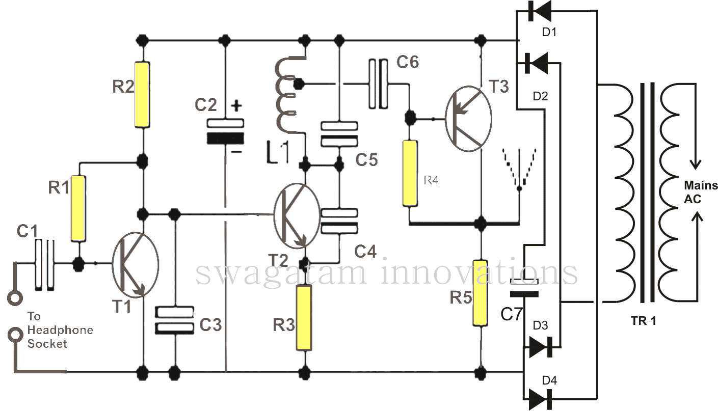
What We Need for Making this System
Now to make this full wireless speaker system work properly, we actually need to build two separate circuit stages.
- One is the transmitter circuit which will take the music or audio signal from your input device (like TV, phone, etc.) and transmit it through air.
- Second is the receiver circuit which will receive that wireless music signal and play it on the connected speaker.
So basically one side is for sending music signal wirelessly, and other side is for catching it and converting into sound on speaker.
Transmitter Circuit Details
Now if we look at the transmitter part shown in the diagram, we can see that this circuit is a bit different from those regular single transistor FM transmitters.
Normally in single transistor transmitters, we use one transistor for doing both jobs – audio amplification and carrier signal generation/modulation.
But here in this design, the setup is not same. It is looking slightly different and more separated stage-wise, so we can expect better signal clarity and better range also.
Why We Don't Use the Usual Single Transistor Design
So normally, many people use the single transistor transmitter circuit because it is small, simple, and consumes very little power. That kind of circuit is really compact and easy to build. But the big problem is – it cannot send the signal very strong or very far. So it is not suitable when we want long distance or strong signal transmission.
But in wireless mic applications, people still use it because there the main focus is only low power and small size, not the range. For mic applications the distance is usually short. So in that case, this single transistor setup works fine and becomes quite suitable.
Why We Need a More Powerful Version
But in our present case, we are not making a wireless mic. We are making one wireless speaker system, so here the small size and low power is not that important. What we really want here is long range and clean, powerful signal transmission, so that our wireless music can reach every part of the room or even go to the next room or apartment.
So because of that, we need to send a much stronger signal. That means we must transmit a more powerful RF carrier wave. Otherwise the speaker will not catch the signal properly.
Thats exactly why in this design, we have added some extra transistor stages, along with the main carrier wave generator. These extra stages help us boost the signal and make the range longer and sound more powerful.
The Audio Amplifier Stage
So in the first part, we are using one transistor with a few supporting parts. This section is working like a neat little audio amplifier and also behaves like a buffer between our music source (like phone, DVD, etc.) and the transmitter section.
This stage increases the weak audio signal to a stronger level. So the next stage can work properly. Also because this stage is doing the amplification, we can keep the volume of our source device at lower level. That helps reduce distortion.
The RF Generator Stage
After the audio is amplified, that strong audio signal is now sent to the next transistor stage. This one is our main RF signal generator.
This section is actually a feedback oscillator which is wired to produce RF signals in the frequency range of around 90 MHz to 100 MHz. This is the standard FM band.
So now what happens – the collector output of the first transistor (T1) sends the strong audio signal to the second transistor (T2) and that modulates the RF carrier wave which is generated by this oscillator.
Making It Even More Powerful
Now, even though this modulated signal coming from collector of T2 can already be used directly for wireless music reception, but still, we are trying to make it more powerful.
So for that, we are adding one more stage. This stage is mainly for boosting the modulated signal to very high level. That way the music can be received across a large distance, like many tens of meters away. Even people can catch the signal in mobile FM radios.
How to Make the Coil L1
Now the coil L1 is very important part in this circuit. It controls the main frequency and range. The specification of L1 is like this:
- Use 1mm super enameled copper wire.
- Wind 5 turns over a 6mm diameter round object (like a pen).
- After winding, you need to scratch a small point on the second last turn of the coil (from positive side end) and take the tap to capacitor C6 from there.
Final Construction Notes
We can build this whole transmitter circuit over a small piece of veroboard and then put it inside one properly sized metal box. Also include a power supply circuit inside that box.
So that completes the transmitter circuit part.
The Receiver Circuit
Now about the receiver side – ideally you may not even need to build any receiver at all. Because this transmitted signal can be heard very clearly on any normal FM radio set. So you can simply use a basic FM radio as the wireless speaker.
If you want more volume then you can connect one ampli-speaker box with your FM radio output and enjoy loud sound.
Final Words
That’s all bro. After everything is done, you will have one powerful wireless speaker system. You can enjoy music wirelessly from your phone or TV, across a distance of 50 meters or more. And if you use a large antenna with the transmitter, the range can easily go up to 90 meters or more.
Parts List
- R1 =1M,
- R2 = 2K2,
- R3 = 470 Ohms,
- R4 = 39K,
- R5 = 470 Ohms,
- C1 = 0.1 uF,
- C2 = 4.7 uF,
- C3, C6 = 0.001uF,
- C4 = 3.3pF,
- C5 = 10pF,
- C7 = 100uF/16V
- D1----D4 = 1N4007
- L1 = See Text
- T1, T2 = BC547B,
- T3 = BC557B
- TR1 = transformer, 0-9V, 100mA
Another Wireless Music Transmitter Circuit
So here below, we are showing one more simple and mini version of FM transmitter circuit. This one also we can use for sending music wirelessly into the air, just like a tiny music radio station from our home.
We just have to connect this circuit directly with any music source, like phone, TV, DVD, computer, etc. Once we do that, then this small transmitter will start pushing that music signal in the air through RF waves.
Then any normal FM radio kept at some distance can easily catch those signals. That FM radio will act like our wireless speaker and it will play the transmitted music loud and clear without using any wires in between.
How to Make the Inductor L1
So now to make the inductor L1, we have to use one piece of super enameled copper wire, and we must follow some exact measurements for making it work properly.
We need to take around 6.5 inches long copper wire, and the wire thickness should be 20 SWG.
Then we take one round object (or a pen-like rod) which has a diameter of around 1/4 inch – that will be our air core former.
Now we take that 6.5 inch wire and slowly wind it over that 1/4 inch round former, turn by turn without any gap between the turns. That is how we make the coil or inductor L1.
This coil is important because it helps to generate the RF carrier frequency properly for sending the music signal through air.
Where the Music Signal is Fed
The music signal which we want to transmit must be connected at the point marked as PL1 in the circuit diagram. That PL1 is the audio input so we connect our phone or DVD player output there.
Leave a Reply