Here in this post we will see how we can make simple automatic solar street light circuits using IC 555, LED, battery, and solar panel, right.
What is an Automatic Solar Street Light System
Now this automatic solar street light system, that is basically a system that checks surrounding light condition and then switches ON or OFF an attached lamp all by itself, depending on how much light is there around, right.
So now in morning when sunlight becomes strong and crosses the set threshold, this system will sense that and quickly turn OFF the connected lamp, ok. At same time the solar panel starts charging the battery, right here.
But then in evening when it becomes dark and light level drops below that set point, system again senses that and switches ON an LED lamp using the stored power from battery, so that place remains bright.
Now this whole ON/OFF cycle keeps happening on its own every day without anyone having to do anything manually, right.
The sensor used here for detecting light is normally a light dependent resistor (LDR), or sometimes it can be a photo-diode or photo-transistor also, ok.
Why Should We Use Automatic Street Light System?
Now why we should use this system? Because it has big benefits.
Saves electricity – This system makes sure lamp never stays ON in daytime when there is already enough sunlight, so power is not wasted.
Saves manpower – Nobody has to switch it ON/OFF every day, system does that all by itself.
Saves money & time – Because no human work is needed so we save effort and cost, making it a great cheap solution.
Very accurate & efficient – Since it works on electronic sensing, its operation is always precise and reliable, ok.
Can We Make This at Home?
Yes of course, we can make this automatic street light circuit at home very easily, using just a few common components.
But one thing, the person who wants to make this should already know some basic electronics and also should be able to solder electronic parts properly, ok.
Solar Street Light Controller Circuit
In some places, there is no AC mains power available, right. So, in such cases, we cannot use AC mains based street light circuits. Thats where a solar-powered automatic LED street light system becomes a smart solution, right.
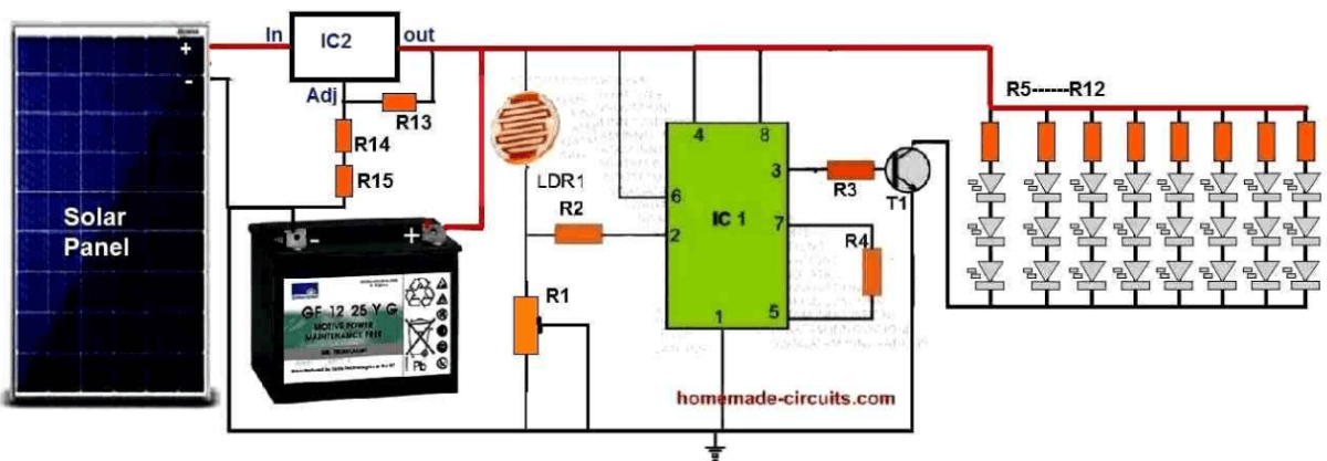
So now the 3rd circuit design below shows how we can make a small solar street light circuit using very few parts.
It is a 24-watt basic setup but we can make it bigger and more powerful as per need, no problem.
Circuit Diagram
Parts List
| Component | Value/Specification | Wattage |
|---|---|---|
| Resistors (1/4 watt unless specified) | ||
| R1 | 1M preset | 1/4 W |
| R2 | 1M | 1/4 W |
| R3 | 875Ω (or 1K) | 1/4 W |
| R4 | 100K | 1/4 W |
| R13 | 150Ω | 1/4 W |
| R14 | 15K | 1/4 W |
| R15 | 33Ω | 1/4 W |
| R5 - R12 | 7Ω | 1W |
| Other Components | ||
| LDR | Any standard LDR | - |
| T1 | TIP142 | - |
| IC1 | 555 IC | - |
| IC2 | LM338 | - |
| Solar Panel | 20V 4A | - |
| Battery | 12V 25Ah | - |
| LEDs | 1W, 3.3V high-bright white | - |
Circuit Working
So now as we already discussed in the last section, this IC 555 we have wired it like a comparator, right.
Now in daytime when there is lots of sunlight, the LDR gets full light so its resistance becomes low and this pulls pin#2 of IC 555 towards the positive supply, ok.
Because of that the output at pin#3 now becomes low and due to this, transistor T1 stays completely shut off, right.
Now with T1 switched OFF, all the LEDs also stay OFF so nothing lights up during daytime, ok.
But then in the evening when it starts getting dark, then LDR also gets less light, so now its resistance starts increasing.
This makes pin#2 of the IC 555 sense a ground potential through R1 so now pin#3 immediately flips to a positive state, right.
Because of this, transistor T1 now turns ON fully and when T1 switches ON, all the LEDs also light up, and this helps brighten the area where this system is installed.
So the circuit successfully works like an automatic street lamp system without needing any manual switching or any external power.
For power, a solar panel is used which charges a battery through a simple voltage regulator made using an LM338 IC, right.
The resistor values we have chosen for this LM338 circuit are set in such a way that the voltage never goes above 14.1V for the battery so this makes sure the battery never gets overcharged, ok.
So during daytime when sunlight is there, then this solar panel keeps charging the battery nicely to a good level.
And then at night, when there is no sun, then this battery starts supplying the stored power to the LEDs keeping them glowing all night, right.
Step by Step Construction
So now here we will see how we can build this automatic solar street light step by step, right. It is very simple but we must do everything properly, otherwise it may not work, okay.
Step 1: Collect All Parts
First we collect all the parts we need, right. We cannot start without them so we make sure we have everything first.
IC1 → 555 Timer IC
IC2 → LM338 voltage regulator
T1 → TIP142 transistor
LDR → Any standard LDR
Battery → 12V 25Ah
Solar Panel → 20V 4A
LEDs → 1W, 3.3V high-bright white LEDs
Resistors → R1, R2, R3, R4, R5–R12, R13, R14, R15
Some wires, PCB, and soldering tools
Without these, we cannot build, so first, we check everything, right.
Step 2: Connect the Solar Charging Circuit
Now here we must set up the solar charging system first because without power nothing will work, okay.
Take LM338 IC and place it properly.
Connect R13, R14, and R15 to LM338. These resistors decide how much voltage will go to the battery, okay.
Connect the solar panel positive to LM338 "IN" pin and negative to ground.
Connect LM338 "OUT" pin to the battery positive terminal.
Now, the battery will start charging in the sun, but never go beyond 14.1V, so it will never get damaged, right.
Step 3: Set Up the Light Sensor Circuit
Now this part is important because it will decide when to turn ON and OFF the LEDs, right.
Place IC 555 properly on the PCB.
Connect pin number eight to positive and pin number one to ground.
Connect LDR and R1, R2 as per the circuit diagram.
Join pin number two to the junction of LDR and R1.
When it is daytime then pin number two will be HIGH and when it is nighttime then it will go LOW, automatically deciding when to switch ON the LEDs, right.
Step 4: Connect the LED Driver Stage
Now we must set up the transistor to control the LEDs, okay.
Connect pin number three of IC 555 to the base of T1 (TIP142) using R3.
Connect T1 emitter to LED negative line.
Connect T1 collector to the positive through resistors R5–R12.
These resistors will limit the current so the LEDs will not burn, okay.
Now, when the transistor turns ON then the LEDs will turn ON, and when it turns OFF then the LEDs will also turn OFF, right.
Step 5: Connect the LEDs
Now we take all the high-bright one watt LEDs and fix them in the right way.
Connect them in series-parallel, just like in the diagram.
Add resistors R5–R12 to each series to control the current.
Join the LED positive ends to the resistors and negative to T1 emitter.
Now when T1 switches ON then all LEDs will glow together, right.
Step 6: Testing the Circuit
Before fixing permanently, we must test properly, or else later we may face problems, okay.
Daytime Test – If the LDR is in light, then check if pin number three of IC 555 is LOW, T1 is OFF, and LEDs are OFF.
Nighttime Test – If the LDR is covered then check if pin number three goes HIGH, T1 switches ON, and LEDs turn ON.
Battery Charging Test – If it is sunlight then check if the battery is charging properly.
Load Test – If it is nighttime then see if the battery supplies enough power to light up the LEDs.
If everything works fine then it is perfect, right.
Step 7: Final Fixing and Installation
Now if all testing is good, then we finalize the setup, okay.
Solder all wires and components properly so that nothing becomes loose later.
Fix everything inside a good waterproof box otherwise dust and rain may damage the circuit.
Install the solar panel at a high place where it gets maximum sunlight.
Fix the LED lamp unit at a proper height so that it can illuminate a large area.
Now we are done! The circuit will automatically turn ON at night and turn OFF in the morning every day, without anyone touching it, right. Simple and effective!
Eliminating the LDR and using the Solar Panel itself to Detect the Ambient Light

Yes, so now we see that removing the LDR completely and just using the solar panel itself for sensing the ambient light is a great idea, right? This way we are reducing unnecessary part, so the design becomes simple and also we use the natural voltage change of the solar panel when sunlight varies.
Modification Steps:
Remove the LDR – We dont need it anymore, so take it out from the circuit.
Use the Solar Panel’s Voltage for Light Detection:
When sunlight is strong (daytime) then the solar panel gives a high voltage, maybe around 18V to 20V.
But at night when there is no sun, then this voltage will drop very low below the battery voltage.
So now we can use this voltage change to decide when to turn the LEDs ON and OFF.
Add a Diode (1N4148) in Series:
We already see this diode in the updated diagram.
This diode is important because it stops the batterys current from flowing back into the solar panel at night.
Modify the 555 Timer Triggering:
The point where the diode and solar panel meet should be connected to pin#2 of the 555 timer.
We have to select R1 and R2 correctly so that the voltage at pin#2 is just right.
In the daytime when the solar panel voltage is high then pin#2 also stays HIGH → 555 output goes LOW → LEDs remain OFF.
But when it gets dark and the solar voltage drops then pin#2 goes LOW - 555 output becomes HIGH - LEDs turn ON.
So now the circuit will smartly detect the ambient light using the solar panel and will switch ON the LEDs only when it is dark.
Leave a Reply