In this article we will attempt to examine some fascinating power supply circuits and associated application circuits using the IC LM338. These circuits can be utilized by hobbyists and professionals alike for their electronic projects and experiments.
Overview
The IC LM338 manufactured by TEXAS INSTRUMENTS is a flexible component that can be connected in various ways to create top-notch power supply circuits.
The circuit examples provided illustrate some of the useful power supply circuits that can be created using this IC.
We should carefully analyze each circuit diagram.
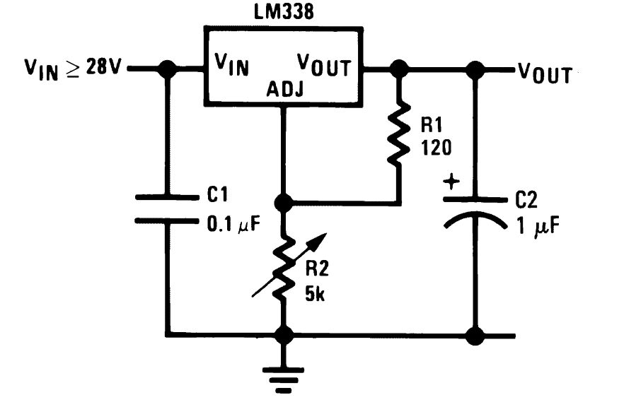
Basic Circuit for Adjustable Voltage Power Supply
The initial circuit displays the standard wiring configuration around the IC. The system allows for a variable output ranging from 1.25V up to the highest input voltage applied not exceeding 35 volts.
R2 is employed to adjust the output voltage in a continuous manner.
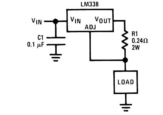
Circuit for a Basic 5 Amp Regulated Power Supply
This circuit controls the current to ensure it never goes beyond 5 Amps while still possibly outputting the same voltage as the input supply. R1 is carefully chosen to ensure a maximum current limit of 5 amps can be safely drawn from the circuit.
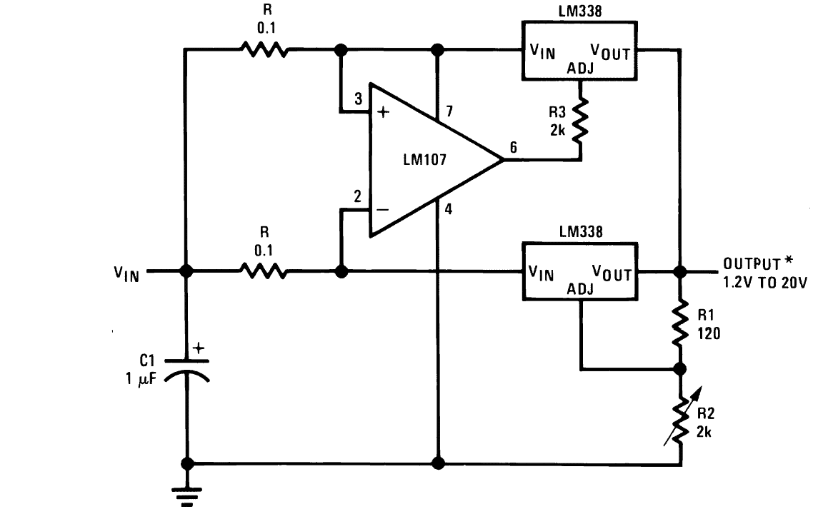
Circuit for Variable Voltage Regulation with 15 Amp Capacity
The LM 338 integrated circuit is designed to handle up to 5 Amps of current but with the right modifications it can be adjusted to handle around 15 Amps.
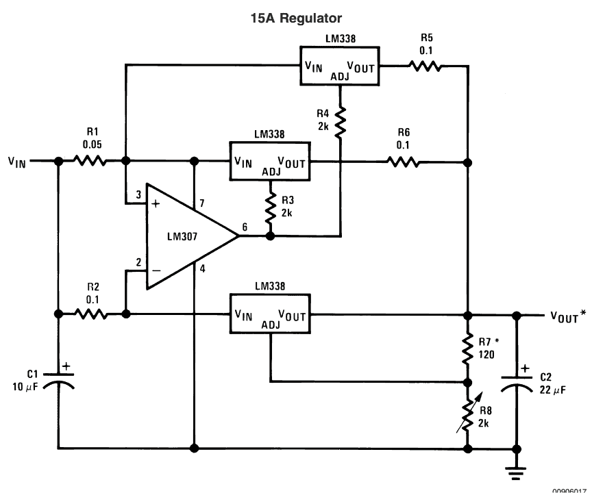
The intended implementations will require the use of three LM338 ICs in the circuit allowing for adjustable output voltage as detailed in the initial design. R8 is employed for carrying out voltage adjustment tasks.
Circuit for a Power Supply that can be Adjusted Digitally:
The power supply in the previous designs used a potentiometer for adjusting the voltage, while the design below uses individual transistors that can be triggered digitally to achieve the desired voltage levels at the outputs.

The values of the collector resistance are selected in a consecutive manner to allow for the selection of correspondingly varying voltages which can be accessed through external triggers.
Circuit for Controlling Light
In addition to being used as a power supply LM338 can also function as a light controller. The design of the circuit is very basic using a phototransistor instead of a resistor to adjust the output voltage.
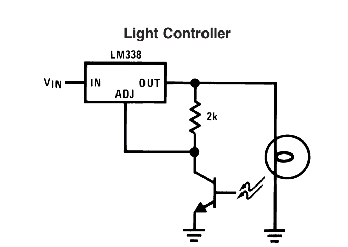
The IC powers the light that needs to be managed and it shines on the phototransistor.
As the brightness grows, the photo-transistors resistance decreases pulling the IC's ADJ pin closer to ground. This lowers the output voltage dimming the light and keeping the lamp glowing steadily.
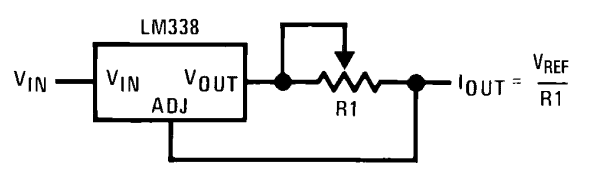
Circuit for Power Supply with Current Control:
The following diagram demonstrates an extremely simplistic connection utilizing the LM338 IC where the ADJ pin is linked to the output following a current sensing preset. The preset value sets the maximum allowable current flowing through the IC's output.
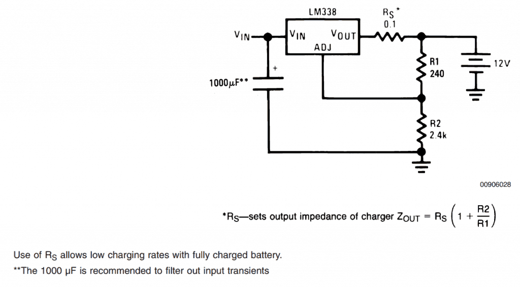
Circuit for Charging Batteries with Current Control at 12V
The following circuit is suitable for safely charging a 12-volt lead acid battery. The resistor Rs can be chosen accordingly to set the desired current level for the attached battery. R2 can be modified to obtain different voltages for charging different types of batteries.
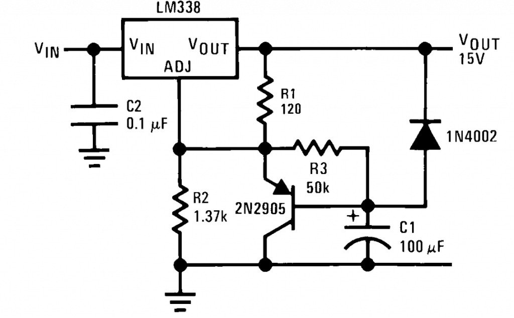
Gradually increase the power supply output.
Certain delicate electronic circuits need a gradual startup instead of the typical immediate startup. Adding C1 ensures that the circuits output gradually increases to the desired maximum level providing the necessary safety for the connected circuit.
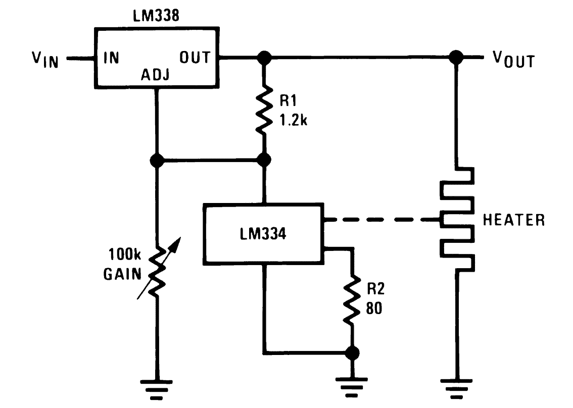
Circuit for controlling the heater.
The LM338 IC can be set up to regulate the temperature of a specific component such as a heating element. Another crucial IC the LM334 serves as the sensor connected between the ADJ pin and ground of the LM338 IC. When the heat rises above the set threshold the sensor reduces its resistance causing the LM338 output voltage to drop leading to a decrease in voltage to the heater element.
Circuit for Regulated Power Supply with 10 Amps
The next diagram depicts a different circuit where the current is limited to 10 amps allowing the output to be configured for high current loads, and the voltage can be adjusted using the potentiometer R2 as usual.
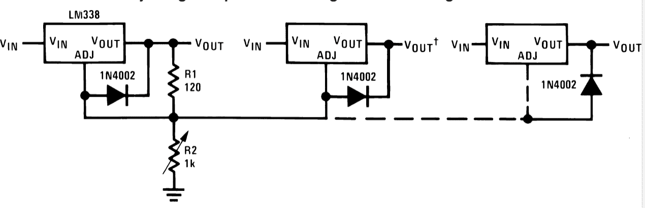
Controlling several LM338 modules with just one adjustment.
The provided circuit displays a basic setup that enables the control of multiple LM338 power supply modules outputs at once using just one potentiometer.
In the previous part we explored some key application circuits involving the LM338 integrated circuit taken directly from the IC's datasheet. If you have additional insights on LM338 circuits feel free to share in the comments section.
Leave a Reply