An inventive method of powering over a hundred white LEDs using a 3.7 volt battery is described in the article. The step-up transformer is driven by the IC 555 in this circuit, and the output of the transformer is then utilized to light the LEDs. The circuit is significantly more power efficient because to a unique PWM design.
Basic Working
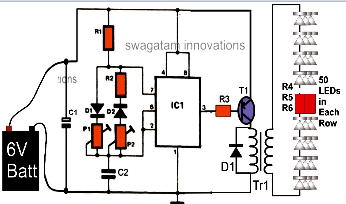
This 3.7V 100 LED PWM driver, which uses an IC 555, consists of two major stages: an output transformer step-up stage and an astable multivibrator stage with PWM control capability.
The PWM stage generates pulses that are used to drain and saturate the transformer's input winding. The output winding of the transformer then amplifies these pulses to the appropriate levels, triggering a number of LEDs that are attached to it.
Efficient PWM Control using IC 555
Wiring the IC 555 as an astable multivibrator is how it is most commonly configured.
With the exception of the two diodes and a few settings, which distinguish the circuit apart from standard 555 astable configurations, every detail regarding the circuit appears to be rather conventional.
In this instance, the two diodes and preset settings allow for distinct control of the pulse forms.
The concept of pulse width modulation, or PWM, refers to this manipulation over the pulses.
By using the schematic and the subsequent information, it is possible to understand how PWM is implemented in the circuit:
As soon as the circuit is first switched on, pin #2, the IC's trigger pin, drops low. This is because the capacitor is in the discharging mode, which keeps the output low.
The output changes from low to high after C2 is completely depleted.
Upon reaching a value across C2 equal to two thirds of the supply voltage, pin #6 of the integrated circuit is flipped, causing the output and pin #7 to drop once more. At this juncture, the capacitor C2 starts charging via D1 and P1.
Circuit Diagram
The output oscillates continuously as a result of the aforementioned process .
That basically implies that one should be able to size the output pulses appropriately by modifying or managing the charging and discharging of C2 independently, as the charging and discharging durations of C2 match directly to the output durations of the pulses.
The PWM mechanism is comprised of the pots, or presets P1 and P2, which are precisely positioned for these modifications.
An additional crucial purpose for this particular application is aided by the PWM application.
We may configure the circuit to provide the best brightness from the LEDs at comparatively reduced battery usage by appropriately adjusting the pulses.
The third pin on the IC is where the output is obtained, and this pin is utilized to drive the power transistor.
Because the power transistor's collector is connected to the secondary (low voltage) winding of a typical AC-DC transformer, the transformer's inductor repeatedly flushes the whole supply voltage into this part of the device.
This induced pulsed voltage into the secondary winding of the transformer causes, accordingly, a corresponding voltage to be induced into the primary winding.
While comparing the scenario to using the transformer for its typical AC-DC adapter applications, the procedure is completely inverted.
Instead of stepping down to around 230 volts, which is its typical primary winding standard, the voltage is boosted up.
Numerous LEDs that are connected in continuous series and several parallel connections are in fact powered by the increased voltage that is provided from the transformer's open winding ends.
Using 3.7V as the Power Source
A 3.7V Li-ion battery with a capacity of about 4 Ah powers the suggested 100 LED Driver circuit.
Despite the battery's seemingly tremendous power, its specifications prevent it from being able to drive a large number of LEDs.
In essence, LEDs are voltage-driven devices rather than current-driven ones; that is, if the applied voltage meets the forward voltage specification, the LEDs light up at modest current magnitudes; conversely, if the voltage falls short of the forward voltage specification, the LEDs remain dark even when the current being used is multiplied by 100.
The fact that LEDs may be operated in series with their minimal required current levels is a further advantage of these devices.
This indicates that the current needed could be roughly equal to what would be needed to illuminate just one LED if the series voltage matched its entire forward voltage.
The requirement for this parameter, or characteristic, in LED wiring arises when the supply voltage is fairly minimal.
Therefore, the rule stated above becomes essential and has been successfully applied for driving a large number of LEDs, as specified for the suggested circuit, using a 3.7 volt supply.
Parts List
The components listed below are needed to build the 3.7V PWM 100 LED driver circuit mentioned above:
All the resistors are ¼ watt unless otherwise specified.
- R1 , R2 = 1 K = 2
- R3 = 10 K = 1
- R4, R5, R6 = 100 Ohms = 3
- P1, P2 = 100 K = 2
- C1 = 10 uF / 25 V = 1
- C2 = 0.001 uF, ceramic disc = 1
- IC = LM 555 = 1
- T1 = TIP 127 = 1
- TR1 = sec. – 0 – 6 V, prim. – 0 – 230 V, 500mA = 1
- Battery – 3.7 volts, 4 AH, Li-Ion =1
- PCB – Veroboard, cut according to the required size = 1
- LEDs – 5 mm, white, high bright, high-efficiency.
Leave a Reply