• Skip to main content
  • Skip to primary sidebar

Making Easy Circuits

Learn and build electronic circuits

You are here: Home / Security and Alarm Circuit / Keypad Lock Circuit using a Single IC

Keypad Lock Circuit using a Single IC

Last Updated on January 10, 2018 by Admin Leave a Comment

The post explains a simple failproof digital keypad security lock circuit using a keypad module and a single CMOS IC .

Introduction

A decimal keyboard, a CMOS IC, about three transistors and an opto-coupler . . . that may be about all that is required to create this electronic lock using a three digit combination.

How the Locking is Triggered

Locking is accomplished using a cascade of analogue switches, every one of which is hooked up, through the programming matrix, to one of the keys on the keypad.

Imagine line A is linked to key 2, line B to key 9, and line C to key 5. When key 2 is currently pushed ES1 closes and remains closed simply because of the current sent to it via R7.

In case key 9 is then pushed ES2 shuts and continues to be closed (due to the fact ES1 has already been closed). At this point all that is required is to click key 5, whereupon ES3 closes hence initiating the opto-coupler, whose transistor subsequently conducts. The keys not utilized in the ABC code need to all be attached to the D line.


keypad lock circuit using a single CMOS IC


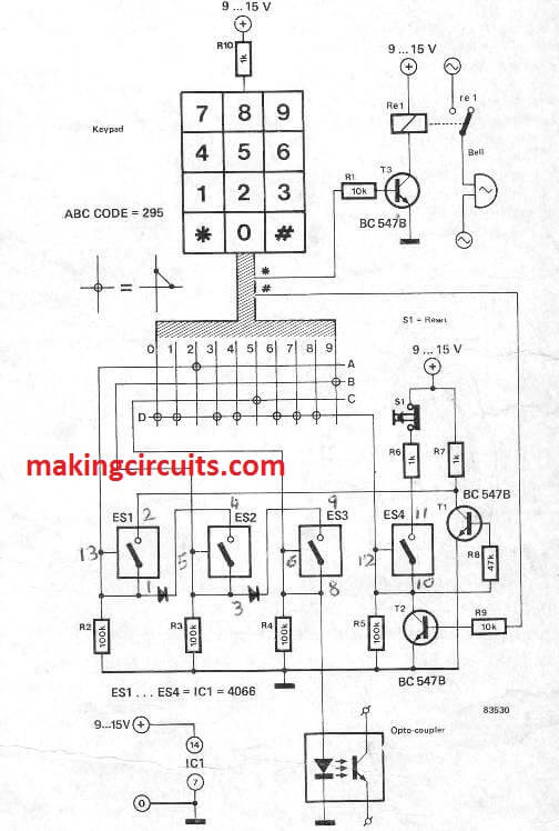
Whenever one of them is pressed, in error or in lack of knowledge, line D sets ES4 to an active high logic level (that it maintains due to R6) and T1 conducts and therefore disables the circuit totally; in reality even though E81 is again turned on, by the pertinent key, it will not auto-hold as long as T1 is executing.

Understanding the Push Button Actions

To begin once again, pushbutton S1 must very first be pressed, hence opening ES4 and stopping T1.

Additionally it is helpful to be able to reset the lock outwardly and this really is accomplished by way of T2, that is attached parallel to the reset circuit and regulated by the. # key. Key * could possibly be applied as an ordinary bell push, triggering relay Re via transistor T3; therefore driving the bell transformer.

One additional statement regarding the functioning of the lock: contemplate again our combination of 295,and believe that ~the first key pressed had not been 2 but 9, that is not wrong, just mislaid.

The B-9 connection leads to ES2 to ciose however it cannot stay closed when key 9 is released due to the fact ES1 is open.

An optocoupler is utilized here in preference some other options that could possibly be picked in some other applications, and testifies to be straightforward, low-cost and efficient in this keypad lock circuit using a Single IC.

You'll also like:

  • 1.  Basic Circuit for Making a Car Burglar Alarm
  • 2.  Simplest Water Level Controller Circuit with Buzzer
  • 3.  Anti-Burglar Home Lighting Circuit
  • 4.  How to Make a Barcode Security Lock Circuit – Part2
  • 5.  Motion Activated PIR Relay Circuit
  • 6.  Simple Smoke Detector Circuit

About Admin

Hey friends, Thanks a bunch for stopping by this site! I am an engineer with a Bachelor of Engineering in Electronics and Telecommunication. One of my passions is gathering information from all sorts of electronics books and tutorials. I then take that information and compile it into a language that is super easy to understand. My goal is to make those complex electronics circuit concepts and technical terms much more accessible for all the new and budding electronics engineers out there. I can also design customized circuit diagrams as required by the users.
If you have any questions related to this field, please do not hesitate to drop a comment! I am always here and ready to help you out with any queries you might have. I cannot wait to hear from you!

Reader Interactions

Leave a Reply Cancel reply

Your email address will not be published. Required fields are marked *

Primary Sidebar

Categories

  • 3 Phase (4)
  • 8051 Microcontroller (1)
  • Arduino (11)
  • Audio and Amplifier (102)
  • Automation (8)
  • Battery Chargers (64)
  • Bicycle Projects (4)
  • Car and Motorcycle Projects (39)
  • Datasheets (10)
  • DIY Projects (5)
  • Electrical (15)
  • Free Energy (6)
  • Games Projects (2)
  • High Voltage (14)
  • Hobby Projects (30)
  • Household Circuits (2)
  • IC 555 Circuits (4)
  • Ignition Circuits (2)
  • Indicators (50)
  • Infrared (6)
  • Inverter Circuits (29)
  • Lights and Lamps (97)
  • Medical (8)
  • Meter and Tester Circuits (38)
  • Motor Driver (17)
  • New Circuits (56)
  • Oscillators (30)
  • Pets and Pests (5)
  • Power supply (81)
  • Protection Circuits (25)
  • PWM (8)
  • Remote Control (20)
  • Security and Alarm Circuit (48)
  • Sensors and Detectors (66)
  • Signal Processor (23)
  • Solar Controller Circuits (61)
  • SSR (3)
  • Temperature Controller (20)
  • Timer (25)
  • Transformerless (7)
  • Transmitters (12)
  • Tutorials (45)
  • UPS (2)
  • Voltage Regulators (57)
  • Water Sensor and Controller (29)
  • Home
  • Privacy Policy
  • Contact
  • Disclaimer
  • Copyright

© 2025 · Making Easy Circuits