The LED Chaser Circuit with Blinker Using IC 4017 is a fascinating project that adds a delightful twist to the traditional LED chaser design. This particular circuit was inspired by a request from Mr. Van, an enthusiastic reader of this blog who wanted something a bit more dynamic.
Initially the circuit was designed to create strobe light effects but with a little tweaking it has now evolved into a versatile LED sequencer (chaser) that also features a blinking capability. The transition between these two modes is seamlessly handled by a toggle switch.
Circuit Operation
Now let us get into the nitty-gritty of how this circuit operates. The IC 4017 is quite the superstar in the world of electronics, it is a Johnson's decade counter/divide by 10 IC that excels in applications requiring sequential output signals.
This means that it can efficiently manage the orderly shifting of outputs based on clock pulses applied to its clock input pin (#14).
Every time there is a rising edge at this clock input then the IC springs into action, moving the positive output from one pin to the next in a predetermined sequence.
To generate these clock pulses we use a couple of NOT gates configured as an oscillator. You can adjust VR1 to control the speed of this sequencing, making it customizable for various applications.
The outputs from the IC are connected to an array of LEDs arranged in a specific order, creating the illusion of lights "chasing" each other as they illuminate sequentially. If you are only interested in producing that chasing effect then you could skip adding diodes altogether.
However since Mr. Van wanted both functionalities, those diodes play a crucial role in allowing the circuit to function as a blinker depending on the position of switch S1.
When S1 is set to position A then the circuit behaves like your classic light chaser, lighting up the LEDs from top to bottom in sequence and repeating this action as long as power is supplied.
But flip S1 to position B and voilà! The clock signals from our oscillator are directed into transistor T1 causing all LEDs to pulsate together in sync with the received clock signals from N1/N2 configuration.
So now we have successfully transformed what started as a simple light chaser circuit into one that can also serve as an LED flasher—how cool is that?
Before you get started building this circuit do not forget to connect the inputs of any unused gates from the IC 4049 either to positive or negative supply rails.
Also ensure that you connect the supply pins of the IC 4049 properly—check out its datasheet for those details.
If your project requires all ten outputs of the IC 4017 for LED sequencing, then simply connect pin #15 of the IC to ground and utilize the remaining outputs for your desired LED sequence: 3, 2, 4, 7, 10, 1, 5, 6, 9, and 11.
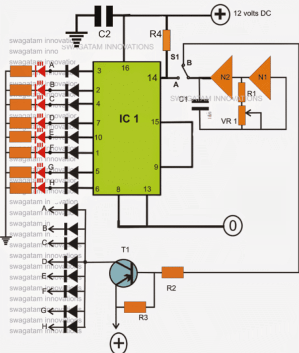
Circuit Diagram
Parts List
| Component | Value/Type |
|---|---|
| R1, R2, R3 | 1K |
| R4 | 100K |
| VR1 | 100K Linear Pot. |
| LED Resistors | 470 Ohms |
| Diodes | 1N4148 |
| LEDs | RED, 5mm (or as per choice) |
| T1 | 2N2907, or BC8550, or BC187 |
| C1 | 10uF/25V |
| C2 | 0.1uF |
| IC1 | IC4017 |
| N1, N2 | IC4049 |
Leave a Reply