So in this post we are looking at a way to make a really neat LED light display like a with different colored LEDs which smoothly fade in and out. Mr. Martin asked for something like this and he wants to avoid using any fancy programmable chips.
Basically we want a circuit where the LEDs light up in a sequence—red, then green, then blue, and so on—with each color fading in after the previous one fades out. It should be a smooth, continuous transition.
Here is the breakdown:
We need equal numbers of red, green, blue, yellow, violet, orange, and white LEDs.
Each color LED should slowly fade in and out.
It would be very nice to control how long each color stays on (light timing), how long it takes to fade in and out (fade in/out timing) and the delay between colors (transition time delay).
Mr. Martin does not want to use any programmable integrated circuits (ICs) but it is okay to use multiple regular ICs if required.
So the goal here is to find out a way to make this cool LED chaser thing happen without using the complicated programmable parts. We need a way to control the timing and fading of the different colors using basic electronic components.
How the Circuit Works
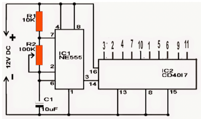
We can understand how it works by checking out the schematic above and reading through this description.
At the top of the circuit we have a standard LED chaser design that includes a decade counter IC 4017 and a clock oscillator made with an IC 555 in an astable configuration.
What happens is that this IC 4017 generates a high logic signal (which is equal to the supply voltage) across all of its output pins. This is in response to the clock signals that come into pin 14 from the IC 555.
Now if we connect the LEDs directly to the outputs of the 4017 and to the ground then the LEDs will light up in a dot-like pattern. They will turn on one after another, starting from the first pin all the way to the last pin, creating that classic chasing effect that many of us have seen or even built ourselves before.
But since Mr. Martin requested something more exciting, we need to enhance this effect by adding a slow transition as the LEDs light up in sequence across the entire setup.
This fading transition on the sequencing LEDs is expected to create a much more interesting group LED chasing effect instead of just having them light up like dots.
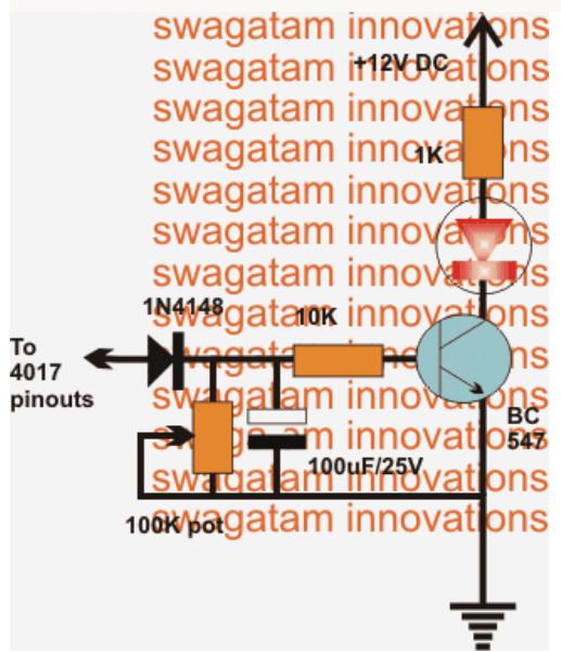
To achieve this cool effect we can easily implement it by connecting the LEDs to an intermediate BJT delay generator circuit. This BJT circuit will be responsible for generating that intended transition delay for when the LEDs illuminate then you can see how it fits into the lower part of the design.
We need to repeat this stage across all of the selected outputs from the 4017 to get that desired chasing and fading slow transition effect over all of the LEDs.
As requested we can control how fast this fading transition happens by adjusting a potentiometer (the pot) that is included in the circuit.
Basically this circuit works as a simple delay timer that keeps each LED lit for a little while longer depending on how we set the value of the pot.
The stored charge on a capacitor creates this timed delay effect for the LEDs and we can choose how long we want it to last based on our preferences.
Additionally we can also change how fast the sequencing occurs by adjusting another pot on the 555 IC. This adjustment can affect the delay transition effect too so it might take some trial and error until we find the most appealing setup.
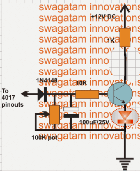
For Improved Fading Effect
If we want an even better fading response then we should connect each LED across the emitter and ground of the circuit, just like what is shown in the diagram below.
Leave a Reply