• Skip to main content
  • Skip to primary sidebar

Making Easy Circuits

Learn and build electronic circuits

You are here: Home / Battery Chargers / Li-Ion Solar Charger Circuit

Li-Ion Solar Charger Circuit

Last Updated on June 14, 2025 by Admin 8 Comments

The article describes a straightforward Li-ion solar charger circuit with automatic cut-off applying transistors mainly.

Solar Charger Circuit using Transistors with Automatic Cut-off

Li-ion simple solar charger circuit

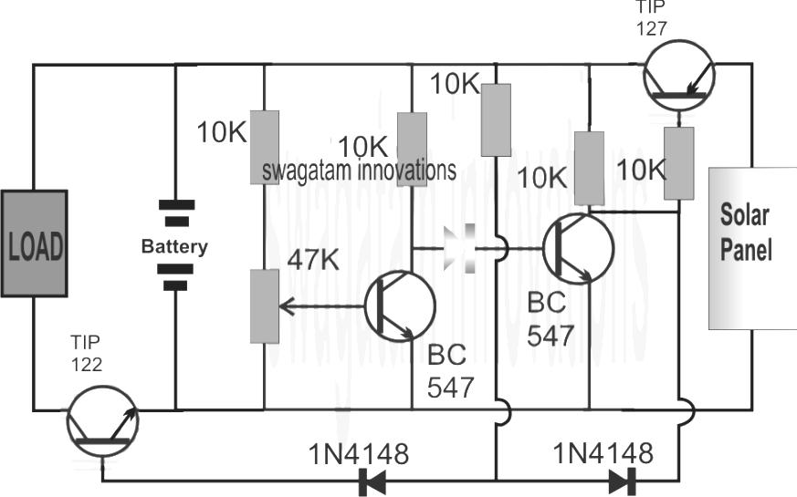
Loking at the above simple solar charger circuit using transistors, the automated cut off for the over charge level and the under level is performed by using a few BJTs put together as comparators.

Remember the earlier low battery indicator circuit employing transistors, in which the lower battery level was portrayed implementing merely a couple of transistors and some additional passive elements.

In this article we hire equivalent design for the detection of the battery levels as well as for reinforcing the specified switching of the battery over the solar panel and the attached load.

Let's believe in the beginning we own a moderately discharged battery that causes the 1st BC547 from left to end conduction (it is fixed through adapting the base preset to this particular limit), and makes it possible for the subsequent BC547 to perform.

The moment this BC547 acts it help the TIP127 to switch ON, which makes it possible for the solar panel voltage to arrive at the battery and start charging it.

The above mentioned circumstance alternatively helps to keep the TIP122 powered down in order that the load cannot function.

As the battery starts out acquiring charge, the voltage throughout the supply track likewise start off increasing right up until a degree in which the left side BC547 is simply in a position to run, evoking the right side BC547 to quit performing any more.

The instant this takes place, the TIP127 is blocked from the negative base signals and yes it steadily ceases conducting in a way that the battery little by little becomes cut-off from the solar panel voltage.

Nonetheless, the above mentioned condition makes it possible for the TIP122 to bit by bit obtain a base biasing trigger and it starts out conducting....that helps to ensure that the load now is capable of getting the specified supply for its procedures.

The above discussed Li-ion Battery solar charger circuit using transistors along with auto cut-offs works extremely well for almost any small range solar controller programs for instance for charging cellphone battery packs or other styles of Li-ion battery packs correctly.

For getting a Controlled Charging Supply

The style may be simply revised for empowering a regulated fixed voltage supply for the battery, as proven beneath:

solar (1)

You'll also like:

  • 1.  Solar Night Lamp Circuit
  • 2.  How to Correctly Calculate Solar Panel, Inverter, Battery Charger
  • 3.  Simple Solar Battery Charger Circuits
  • 4.  Charging Two Batteries from a Single Supply Source
  • 5.  Understanding Solar Panels Voltage, Current Specs
  • 6.  Precision Solar Battery Charger using Comparator

Tagged With: Charger, ion, Solar

About Admin

Hey friends, Thanks a bunch for stopping by this site! I am an engineer with a Bachelor of Engineering in Electronics and Telecommunication. One of my passions is gathering information from all sorts of electronics books and tutorials. I then take that information and compile it into a language that is super easy to understand. My goal is to make those complex electronics circuit concepts and technical terms much more accessible for all the new and budding electronics engineers out there. I can also design customized circuit diagrams as required by the users.
If you have any questions related to this field, please do not hesitate to drop a comment! I am always here and ready to help you out with any queries you might have. I cannot wait to hear from you!

Subscribe
Login
Notify of
8 Comments
Newest
Oldest Most Voted
Inline Feedbacks
View all comments
Nelio
1 year ago

Hi,
What is the minimum input voltage for this circuit?
Nelio

0
Reply
Author
Admin
1 year ago
Reply to  Nelio

It is 3v…

0
Reply
Nelio
1 year ago

Hi,
Do I need to do any changes in order to charger a 3.7V Li-Ion Battery?
Nélio.

0
Reply
Author
Admin
1 year ago
Reply to  Nelio

Hi, you can replace all the 10k with 2.2k

0
Reply
Nelio Abreu
1 year ago

Hi,
What is the purpose of the LED?
In which conditions does it light up?

0
Reply
Author
Admin
1 year ago
Reply to  Nelio Abreu

Hi, It shows the battery is charging…

0
Reply
Richard Goss
2 years ago

what is the diode no. that is in red on schematic

0
Reply
Author
Admin
2 years ago
Reply to  Richard Goss

There is no red colored part in the above schematic….but there is an LED at the center

0
Reply

Primary Sidebar

Categories

  • 3 Phase (4)
  • 8051 Microcontroller (1)
  • Arduino (11)
  • Audio and Amplifier (103)
  • Automation (8)
  • Battery Chargers (64)
  • Bicycle Projects (4)
  • Car and Motorcycle Projects (40)
  • Datasheets (10)
  • DIY Projects (6)
  • Electrical (15)
  • Free Energy (6)
  • Games Projects (2)
  • High Voltage (14)
  • Hobby Projects (30)
  • Household Circuits (2)
  • IC 555 Circuits (4)
  • Ignition Circuits (2)
  • Indicators (51)
  • Infrared (6)
  • Inverter Circuits (29)
  • Lights and Lamps (97)
  • Medical (8)
  • Meter and Tester Circuits (38)
  • Motor Driver (17)
  • New Circuits (56)
  • Oscillators (30)
  • Pets and Pests (5)
  • Power supply (84)
  • Protection Circuits (25)
  • PWM (8)
  • Remote Control (20)
  • Security and Alarm Circuit (48)
  • Sensors and Detectors (66)
  • Signal Processor (23)
  • Solar Controller Circuits (61)
  • SSR (3)
  • Temperature Controller (20)
  • Timer (25)
  • Transformerless (7)
  • Transmitters (12)
  • Tutorials (45)
  • UPS (2)
  • Voltage Regulators (57)
  • Water Sensor and Controller (29)
  • Home
  • Privacy Policy
  • Contact
  • Disclaimer
  • Copyright

© 2025 · Making Easy Circuits

wpDiscuz