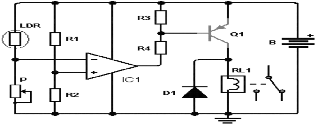
This light activated switch circuit, automatically switches ON a connected lamp when night falls, and switches it OFF during day break.
It has many applications, it could be used as a photocell and to off the light in a room or turn on the radio when it is dawning, etc. Working of light activated switch.
How the Circuit Works
The photoresistor / LDR whose ohmic value varies depending on the amount of light that may be incident upon its surface. A network of two resistors (R1 and R2) of equivalent value, causes the voltage at the non-inverting terminal of operational be 6 volts.
If the LDR is not illuminated, its resistance is high and causes the voltage at the non-inverting terminal of the operational amplifier, drops below 6 volts. The output of the operational amplifier is high, the transistor Q1 is off and the relay is not active.
When as soon as the LDR is illuminated, resistance and voltage across its terminals decreases to a lower value, causing the voltage at the inverting terminal of the opamp to increase over exceeding 6 volts. The value of LDR is not critical at all.
The pot P is adjusted so as to have the same ohmic value just as the LDR, under all normal conditions. The supply battery can be 12 or 9 volt.

Notes: LDR photoresistor = photoresistor
List of components for the Light Activated Switch Circuit
- IC1: operational amplifier 741
- Q1: PNP transistor 2N3702 or equivalent
- R1 = R2: 10K resistors
- R3 = R4: 1.2K resistors
- P: potentiometer is worth approximately twice the LDR
- D1 Diode 1N4001 or equivalent
- LDR: photoresist of any value
- 1 relay (relay) 9 Volt (B = 12V) or 6 volts (B = 9V), with the winding resistance as high as possible, (500 ohms or more)
Leave a Reply