• Skip to main content
  • Skip to primary sidebar

Making Easy Circuits

Learn and build electronic circuits

You are here: Home / Audio and Amplifier / Make this Booming Pistol Sound Simulator Circuit

Make this Booming Pistol Sound Simulator Circuit

Last Updated on January 12, 2025 by Admin Leave a Comment

The oscillator circuit that is being suggested is made to produce a loud, pistol-like boom that can be heard over a loudspeaker.

This circuit for a gun sound generator may be employed to generate a button-operated start sound for running races or events involving racing, or it might be utilized to just scare off robbers and wild creatures in isolated locations.

Since noise pollution is harmful to one's health, the idea might also be used successfully to create a loud, fake cracker sound during festivities like Diwali.

gun shot

Image source: https://en.wikipedia.org/wiki/Weaver_stance#/media/File:US_Navy_031104-N-1693W-038_Electronics_Technician_3rd_Class_Jeremy_Aragon_practices_drawing_and_firing_the_M9_Beretta.jpg

The circuit creates the loud, booming gun sound by using a 60-watt loudspeaker that was abandoned.

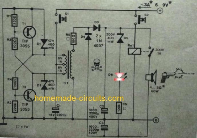
In addition with the mains transformer TR1, T1 and T2 constitute the primary parts that make up the power oscillator circuit.

Using a single button press, S1 is utilized to temporarily start or power up the circuit stage mentioned above.

The necessary protection towards inductive voltage surges is given to the transistors by the zener diodes.

The core substance of the transformer and the amount of current extracted from the secondary of the transformer define the oscillator circuit's frequency because it is a self-oscillating circuit.

The Circuit's Function

By pressing S1 causes the circuit to oscillate at a comparatively high frequency, and this eventually drops to about 50 Hz once C1 and C2 are charged.

The connected diodes D3 and D4 provide a voltage doubler setup, while the resistor R5 restricts the current to allowable limits.

To generate hundreds of volts across the connected relay contacts, a voltage doubler circuit is added.

When switches C1 and C2 have been completely charged, the LED D6 illuminates, signaling that S1 is currently withdrawn and that switch S2 is prepared for activation.

The relay activates immediately the "fire" button S2 is pressed, turning on its contacts. This causes an immediate enormous amount of current and voltage to discharge across the loudspeaker coil, producing the necessary hammering gun sound. It is necessary to make sure that the speaker coil is suitably rated to manage this enormous, sudden power surge.

After pushing S2, current draw may be approximately 3 amps, but when C1 and C2 discharge to their minimum limits, it progressively drops to about 0.5 amps.

By increasing the supply voltage to around 12V, the handgun sound generator's decibels or "bang" intensity may be correspondingly increased.

The suggested handgun sound simulator circuit's full circuit diagram is shown below:

pistol sound simulator circuit

You'll also like:

  • 1.  Small Transistor Amplifier Circuit
  • 2.  Subwoofer Amplifier Circuit – High Power
  • 3.  Simplest FM Radio Circuit with High Reception Quality
  • 4.  DIY Guitar Jammer Circuit: Mix Tracks and Play Like a Pro
  • 5.  How to make a Simple Music Box Circuit
  • 6.  Music Stroboscope Circuit

About Admin

Hey friends, Thanks a bunch for stopping by this site! I am an engineer with a Bachelor of Engineering in Electronics and Telecommunication. One of my passions is gathering information from all sorts of electronics books and tutorials. I then take that information and compile it into a language that is super easy to understand. My goal is to make those complex electronics circuit concepts and technical terms much more accessible for all the new and budding electronics engineers out there. I can also design customized circuit diagrams as required by the users.
If you have any questions related to this field, please do not hesitate to drop a comment! I am always here and ready to help you out with any queries you might have. I cannot wait to hear from you!

Reader Interactions

Leave a Reply Cancel reply

Your email address will not be published. Required fields are marked *

Primary Sidebar

Categories

  • 3 Phase (4)
  • 8051 Microcontroller (1)
  • Arduino (11)
  • Audio and Amplifier (102)
  • Automation (8)
  • Battery Chargers (64)
  • Bicycle Projects (4)
  • Car and Motorcycle Projects (39)
  • Datasheets (10)
  • DIY Projects (5)
  • Electrical (15)
  • Free Energy (6)
  • Games Projects (2)
  • High Voltage (14)
  • Hobby Projects (30)
  • Household Circuits (2)
  • IC 555 Circuits (5)
  • Ignition Circuits (2)
  • Indicators (50)
  • Infrared (6)
  • Inverter Circuits (29)
  • Lights and Lamps (97)
  • Medical (8)
  • Meter and Tester Circuits (38)
  • Motor Driver (17)
  • New Circuits (56)
  • Oscillators (30)
  • Pets and Pests (5)
  • Power supply (80)
  • Protection Circuits (25)
  • PWM (9)
  • Remote Control (20)
  • Security and Alarm Circuit (48)
  • Sensors and Detectors (66)
  • Signal Processor (23)
  • Solar Controller Circuits (62)
  • SSR (3)
  • Temperature Controller (20)
  • Timer (25)
  • Transformerless (7)
  • Transmitters (12)
  • Tutorials (45)
  • UPS (2)
  • Voltage Regulators (57)
  • Water Sensor and Controller (29)
  • Home
  • Privacy Policy
  • Contact
  • Disclaimer
  • Copyright

© 2025 · Making Easy Circuits