• Skip to main content
  • Skip to primary sidebar

Making Easy Circuits

Learn and build electronic circuits

You are here: Home / Indicators / Loudspeaker Power Indicator Circuit

Loudspeaker Power Indicator Circuit

Last Updated on July 1, 2020 by Admin Leave a Comment

This circuit will reveal the height level of an input signal placed on a speaker.

It is mainly meant as a fool proof device when linked to an amplifier of higher power rating compared to speaker.

The loudspeaker power indicator circuit is exclusive in this no distinct DC power supply is essential because the circuitry functions through the input voltage to the speaker.

fig1 2

R5 isolates the amplifier's output stage from possible error situations in the circuit. D1 to D4 full wave rectify the input signal and also causing DC is utilized to provide the op amp.

The 741 is employed as a comparator a reference voltage is extracted from ZD3 and fed into the inverting input of the op amp. The non inverting input samples the rectified input signal.

When a peak reaches the loudspeaker power indicator circuit the IC's output goes high and the led flashes. ZD1 stops the LED switching on once the output of IC1 is low as a result of output being ineffective to go lower than 1.5V higher than ground under these situations.

ZD2 describes the upper threshold of the op amp's supply voltage in the existence of large transients whilst R2 acts as the current limit resistor.

It needs to be apparent that the level from which the led lights depends upon the R3 value.

The associated table displays the value needed for this part for various input powers across an 8 ohm load.

If several load values need to be employed for the speaker the value of R3 could be established through the formula:
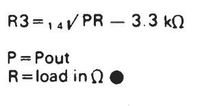
for

You'll also like:

  • 1.  3 in 1 Circuit Fault Tester Circuit
  • 2.  Keyboard Beep Circuit
  • 3.  Office Bell with IN/OUT Indicator Circuit
  • 4.  Coffee Temperature Indicator Circuit
  • 5.  Designing Large LED Dispay Circuit
  • 6.  Test Logic with this Logic Probe Circuit

About Admin

Hey friends, Thanks a bunch for stopping by this site! I am an engineer with a Bachelor of Engineering in Electronics and Telecommunication. One of my passions is gathering information from all sorts of electronics books and tutorials. I then take that information and compile it into a language that is super easy to understand. My goal is to make those complex electronics circuit concepts and technical terms much more accessible for all the new and budding electronics engineers out there. I can also design customized circuit diagrams as required by the users.
If you have any questions related to this field, please do not hesitate to drop a comment! I am always here and ready to help you out with any queries you might have. I cannot wait to hear from you!

Reader Interactions

Leave a Reply Cancel reply

Your email address will not be published. Required fields are marked *

Primary Sidebar

Categories

  • 3 Phase (4)
  • 8051 Microcontroller (1)
  • Arduino (11)
  • Audio and Amplifier (102)
  • Automation (8)
  • Battery Chargers (64)
  • Bicycle Projects (4)
  • Car and Motorcycle Projects (39)
  • Datasheets (10)
  • DIY Projects (5)
  • Electrical (15)
  • Free Energy (6)
  • Games Projects (2)
  • High Voltage (14)
  • Hobby Projects (30)
  • Household Circuits (2)
  • IC 555 Circuits (5)
  • Ignition Circuits (2)
  • Indicators (50)
  • Infrared (6)
  • Inverter Circuits (29)
  • Lights and Lamps (97)
  • Medical (8)
  • Meter and Tester Circuits (38)
  • Motor Driver (17)
  • New Circuits (56)
  • Oscillators (30)
  • Pets and Pests (5)
  • Power supply (80)
  • Protection Circuits (25)
  • PWM (9)
  • Remote Control (20)
  • Security and Alarm Circuit (48)
  • Sensors and Detectors (66)
  • Signal Processor (23)
  • Solar Controller Circuits (62)
  • SSR (3)
  • Temperature Controller (20)
  • Timer (25)
  • Transformerless (7)
  • Transmitters (12)
  • Tutorials (45)
  • UPS (2)
  • Voltage Regulators (57)
  • Water Sensor and Controller (29)
  • Home
  • Privacy Policy
  • Contact
  • Disclaimer
  • Copyright

© 2025 · Making Easy Circuits