The mains surge suppressor filter explained here is actually a type of passive low-pass filter which has a roll-off frequency of 50 Hz. This unit can be efficiently used as a computer power strip for protecting computers against switch ON surge interference and other similar issues.
It is quite frustrating but normally undeniable fact that a lot of mains-operated devices generate electrical spikes and surges along with other interference over the mains wiring. However, getting rid of undesirable issues such as popping noises from AF equipment as the fridge switches on, or perhaps a personal computer ceasing to function while the equipment and lighting are turned on may not be as difficult as it may appear. All that is required to protect against such infuriating effects is actually a good-quality mains surge suppressor or filter network.
The design may appear similar to an audio low pass filter, but actually it’s not due to the fact that the high working voltage and the attached factors in regards to security govern the application of exclusive parts.
Across the world, specifications happen to be established that determine the maximum capacitor values employed in such filters, usually based on whether or not mains-powered devices are wall- or floor-mounted, or portable.
Capacitors are Crucial
All these capacitor values are generally a cautiously proven compromise between appropriate switch-on and switch- off currents on one side, and the potential for electrical shock with regards to substandard or incorrectly hooked up earthing or the capacitors on their own are unable to protect the specified slope steepness of the filter.
The attenuation beyond the pass-band is increased substantially by employing several chokes. These can be found in a minimum of three versions, on the whole, the choke having the greatest inductance value is among the most effective. Nonetheless, if reactive loads are operated, the voltage drop over the choke increases with inductance.
In real life, this indicates that the surge filter needs to be designed precisely according to the load and the evaluated characteristics of the mains interference. The easiest model may be the saturation choke. As soon as the mains power is started up, this kind of inductor offers an increased inductance, that quickly drops as the current causes ferrite core saturation.
The interference suppression grade is practically mostly as stipulated for symmetrical (balanced) interference, which is, interference that is present across the phase and the neutral lines of the mains.
How the Torroid Inductor Helps Suppression
The multiple-winding current-compensated torroid choke works more effectively but in addition it’s a lot more costly compared to saturation variety. Strong capacitive coupling between the circuit and the housing results in an unbalanced current (between L/N and E) to move into the home appliances from the earthing wire, and 50 % of is fed back into the mains line through the live or neutral wiring.
The short incomplete interference current burst causes the choke windings placed in series with the phase or neutral line, to get damped leading to magnetic fields being created within the windings terminating each other.
The inductance of both chokes react with the load current which leads to a little drop in the voltage. The bar-type choke is the most suitable for loads more than 100 A which develop largely symmetrical interference (between live and neutral). As opposed to the saturation type choke, the inductance of a bar-type choke is more stable.
Practical circuit
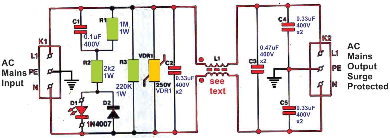
The circuit diagram of the mains surge suppressor is given in Fig. 1. The mains voltage is input is implemented via connector K1. Parts C1 and Rr work like a potential divider for the on/off lamp, D1. Capacitor C1 gets discharged via R1 when the device is unplugged from the mains.
Diode D2 across D1 is positioned to ensure that the reverse voltage over the LED is restricted inside safe limits. Voltage peaks beyond 250 V are instantly neutralized by varistor VDR1. Capacitors C2 and C1 has to be class-X2 types. In the same way, C4 and C5 should be of class-Y category.
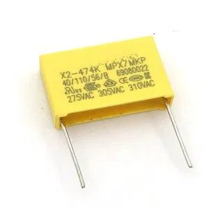
Capacitors
These codes point out an a.c. working voltage in the range of 250 V and assign to metallized polyester or polypropylene capacitors having excellent self-healing qualities in an event of arcing within the dielectric material. X2-class capacitors is probably not applied to situations where their malfunction could risk n individual to an electric shock.
As a result, these types of capacitors are used between the live and neutral lines to guarantee that breakdown can cause no more than just a burnt fuse (when it comes to a short-circuit) or decreased filtering operation (with regards to an open-circuit).
Each of these issues can be a lot irritating although not hazardous. The necessities of the Y-type capacitors, C4 and C5, tend to be more exacting (see B.S. 6201, part 3, and IEC161). Just like C2 and C3, these lead to low quality suppression during an open-circuit malfunction.
More significantly, in case of a short-circuit in both C4 or C5 causes the live (L) or neutral (N) line to get shorted to the protective earth line. Therefore it is strictly recommended to adhere to the following warning:
Under no circumstances use capacitors having a an alternative type or rating, not complying to the advised specification.
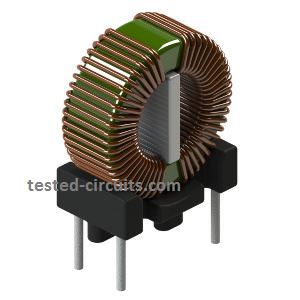
Inductor Filter
The inductor filter included the surge suppressor circuit is made using a current-compensated choke. The PCB provides the facility for fitting two of these inductors. These types vary according to the maximum load current and inductance values. The 2 x 10 mH inductor Type RD62-3 is graded for up to 3 Amp current, and the 2 x 4 mH Type RD62-6 is rated to work with up to 6 Amp current.
Hi John. Thanks for the comment but how should C4 and C5 be connected in the circuit
Although C4 and C5 are correctly described as Y class capacitors in the text, they are INCORRECTLY marked on the circuit diagram. In the event of an earth connection failure, X class capacitors for C4 and C5 could result in electric shock as they are designed to fail short circuit.
Thanks very much for sharing your feedback, I hope the readers will note the mistake and correct the diagram accordingly.