We've already been implementing this opamp IC most likely ever since we were children, I have been talking about this amazing little IC 741, by which almost any circuit developing turns into achievable. It nearly on your own has the capacity to manage numerous difficult features and creates circuit configuration very simple, that's why its considered one of the favourite chips not only with the new electronic hobbyists but in addition with the skilled engineers.
Here we are talking about one of the easy application circuits of this IC where it has been configured as a comparator, no surprise the following applications could be improved in many different various methods as per the user desire.
As the name indicates, to make a 741 opamp comparator represents the function of comparing between a specific set of guidelines or may be just a few magnitudes as in the case.
Since in electronics we are mainly coping with voltages and currents, these aspects turn out to be the sole agents and are used for working or regulating or managing the numerous parts included.
In the recommended opamp comparator design, where the IC 741 is being made use of as a comparator, basically different voltage levels are utilized as the referring and comparaing guidelines by the IC.
The two input pins referred to as the inverting (with a minus sign)and the non-inverting pin (with a + sign) turn out to be the sensing inputs of the IC 741.
When utilized as a comparator, one of the pins out of the two is applied with a fixed reference voltage while the other pin is fed with the voltage whose level ought to be checked.
The supervising of the above voltage is done with respect to the fixed voltage that's been put on to the other complementary pin.
Therefore if the voltage which is to be supervised turns out above or drops below the fixed reference threshold voltage, the output reverts state or changes its original condition or changes its output voltage polarity.
Let's examine the above justification by researching the following illustration circuit of a light sensor switch.
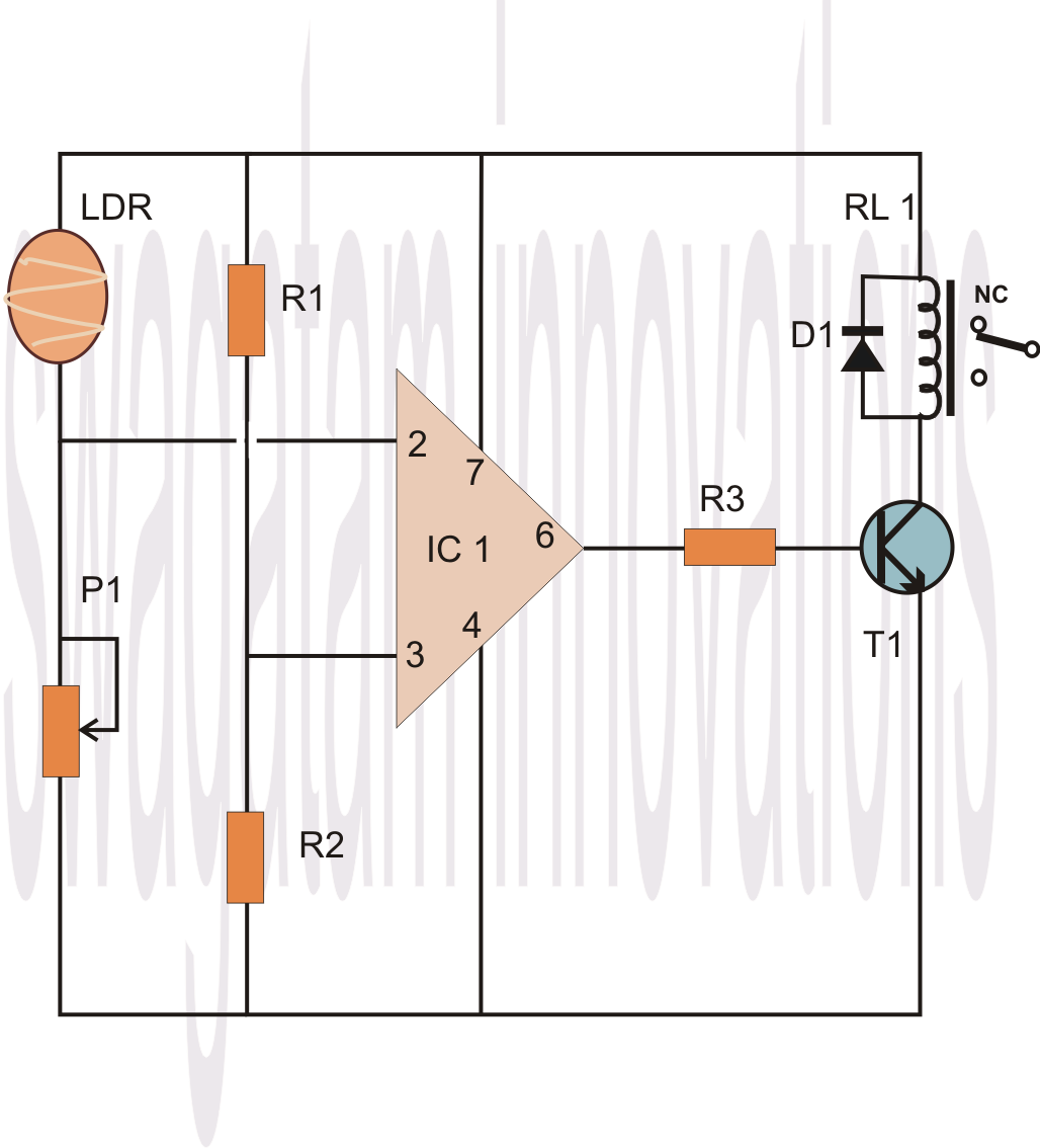
Considering the 741 opamp comparator circuit diagram we come across the circuit set up in the following manner:
The IC 741 is at the center.
Its Pin #7 which is the +supply pin is hooked up to the positive rail, in the same way its pin #4 which is the negative supply pin is hooked up to the negative or rather the zero supply rail of the power supply.
The above couple of pin connections powers the IC so that it can continue with its meant features.
At this point as mentioned earlier, pin #2 of the IC is hooked up at the junction of two resistors whose ends are connected to the power supply positive and negative rails. This arrangement of the resistors is known as a potential divider, meaning the potential or the voltage level at the junction of these resistors will be roughly the half of the supply voltage, so if the supply voltage is 12, the junction of the potential divider network will be 6 volts and so on.
If the supply voltage is well controlled, the above voltage level may also be well fixed thereby can be utilized as the reference voltage for the pin #2.
So if we take 6 as the junction voltage of the resistors, this voltage turns into the reference voltage at pin #2 which suggests the IC will monitor and react to any voltage which may go above this level.
The sensing voltage which can be to be supervised is placed on pin #3 of the IC, in our instance it is via an LDR. The pin #3 is hooked up at the junction of the LDR pin and a preset terminal.
Which means this junction again turns into a potential divider, whose voltage level this time is not fixed because the LDR value simply cannot be fixed and will vary with the ambient light conditions.
Now think you would like the circuit to feel the LDR value at some point just around when dusk drops, you regulate the preset such that the voltage at pin #3 or at the junction of the LDR and the preset just exceeds above the 6 volt mark.

When this occurs the value increases above the fixed reference at pin #2, this updates the IC about the sense voltage increasing above the refefnce voltage at pin #2, this immediately reverts the output of the IC which changes to positive from its initial zero voltage position.
The above change in the state of the IC from zero to positive, generates the relay driver phase which switches ON the load or the lights which happen to be linked to the pertinent associates of the relay.
Mind you, the values of the resistors attached to pin #2 can also be modified for changing the sensing threshold of pin #3, so they are all inter-depended, giving you a wide angle of variation of the circuit parameters.
Another feature of the R1 and R2 is that it prevents the need of utilizing a dual polarity power supply making the required configuration quite simple and clean.
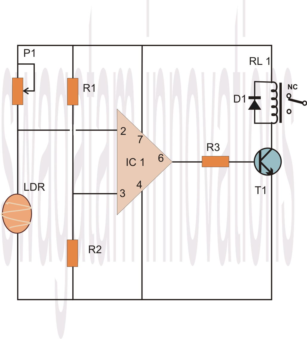
As presented below, the above described procedure reply could be just corrected by interchanging the input pin positions of the IC or, by thinking about another alternative where we only inter-change the positions of the LDR and the preset.

How to make a 741 opamp comparator circuit

Leave a Reply