Let’s face it, mosquitoes are some of the most annoying bugs out there. They not only bug us like crazy but they also have the potential to spread some really serious diseases. It feels like they just keep coming back no matter how hard we try to get rid of them.
We’ve got tons of methods available today to deal with these pesky insects. Think about it, we have those electrocuting bats, mosquito-repelling creams, coils, and mats, among other things. While these options might seem effective none of them really feel like the perfect solution to completely wipe them out.
But here’s where it gets interesting—there’s another method that’s a bit controversial but could actually be one of the most effective ways to keep mosquitoes away especially if we can optimize the results just right. We’re talking about using frequency generation to drive those mosquitoes off.
The Science Behind It
Researchers have discovered that bugs and insects are often sensitive to a specific range of frequencies known as ultrasound frequencies. Now this is important because these frequencies are beyond what we humans can hear but they can create a lot of discomfort for insects and even for our pets like dogs and cats.
While some people might debate this method, there are scientists and many others who swear by it as a useful way to control mosquitoes.
In this discussion we’re going to look at a sample circuit that has been specifically designed to generate sound at those ultra-high frequency levels.
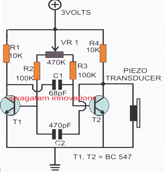
How the Circuit Works
Now lets talk about how this electronic mosquito repellent circuit works. I wouldn’t say it’s the ultimate solution for all our mosquito problems but it definitely leaves room for us to experiment and improve it.
If we can get everything set up just right and hit that sweet spot we might just get lucky! The concept is pretty straightforward and doesn’t require anything fancy, just a couple of transistors, some capacitors, and a few resistors is all we need.
We set up the circuit as an astable multivibrator, and the components we choose will make the circuit oscillate at our desired frequency. We’have intentionally created a slight imbalance in symmetry by using different capacitor values so that the waveform generated is symmetrical. This symmetry is key for achieving the results we want.
The frequency is then outputted through a piezoelectric transducer, which is great at interpreting high-frequency sounds.
To really make this work for us we should try adjusting the potentiometer at different levels and testing it out in areas where mosquitoes are swarming around.
We can keep optimizing it until hopefully we start seeing some positive results, like actually watching those mosquitoes take off in the other direction!
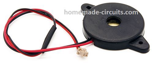
Piezo Transducer
Replacing the Piezo Transducer with a Crystal Earpiece
So here’s something interesting about mosquitoes and other annoying insects... they only seem to mate during certain times and when it’s not mating season the males and females are pretty hostile toward each other. They keep their distance and avoid one another like the plague.
Now here’s another fun fact: it’s actually the female mosquitoes that do the biting. They’re the ones that really sting us!
Another thing we need to grasp is that male mosquitoes (and some other bugs too) flap their wings at a different rate compared to females. This difference in wing flapping is a big part of how they can tell each other apart.
With all this in mind we can figure out that if we could electronically mimic the sound of a male mosquito's wings we might just be able to scare off those pesky females. How cool would that be?
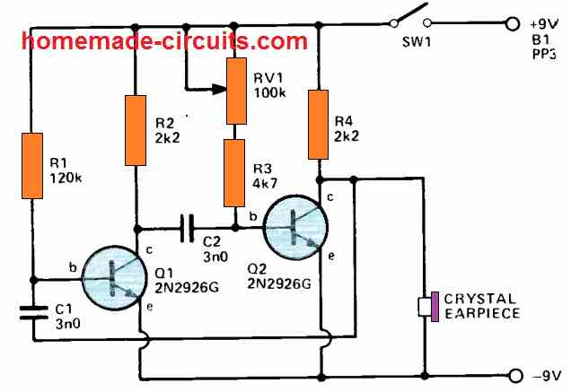
The above design is basically a simple audio oscillator that we can adjust to operate at a wide range of frequencies—specifically from about 500Hz all the way up to 10kHz.
This range pretty much covers the frequencies that most typical bugs are sensitive to. The circuit itself is a straightforward multivibrator, and we can tweak the audio frequency using RV1.
What happens is that this setup generates a square wave which gets sent through a tiny crystal earpiece connected to the negative line and the collector of Q2. Now even though the impedance of those crystal earpieces is pretty high it doesn’t mess with how well the circuit works.
You can use just about any transistor for this basic circuit, but if you decide to go with PNP types, remember that you’ll need to flip the battery supply around.
When it comes to capacitor values they’re not super critical. If you try different capacitor values and find that the frequency range isn’t quite right you can adjust R1 to get it back into the recommended range.
The good news is that this circuit uses very little current—around 2-2mA—and it varies a bit with frequency. This means that a PP3 battery can last us quite a while since we want our device to stay on for extended periods.
We can build this little gadget in a compact box that fits nicely in our coat pocket making sure to arrange the parts so that the earpiece is on the outside. Plus we want to keep all the components as small as possible. Its really all about trial and error to find that perfect frequency that drives those mosquitoes away most effectively!
Leave a Reply