Here we are making a simple automatic street light circuit that can turn ON a lamp when it gets dark and turn it OFF when there is daylight. You do not have to press any switch because the circuit will sense the light and do it by itself.
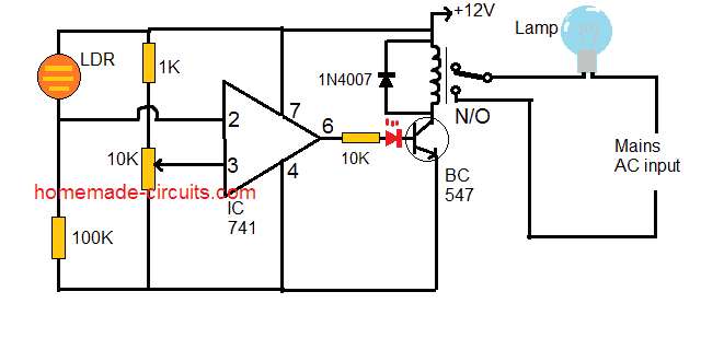
We are using an LDR (Light Dependent Resistor) as a light sensor, an IC 741 op-amp to compare voltage, a BC547 transistor to act like a switch and a relay to control the AC lamp. When it becomes dark then the LDR tells the op-amp, which then turns ON the transistor which then activates the relay and finally the lamp turns ON. When it is daytime then everything happens in reverse, and the lamp turns OFF.
This circuit is useful for street lights, garden lights or any outdoor lighting where you want an automatic system without manual switching. Now let us see how it works and how we can build this step by step.
How It Works:
When It Is Daytime (There Is Bright Light), Then:
The LDR sees the light so its resistance drops.
Because of this, the voltage at pin 2 of the op-amp increases.
Now pin 2 has a higher voltage than pin 3, so the op-amp output at pin 6 remains LOW.
Since the output is LOW then the transistor does not turn ON so the relay stays OFF.
The relay contacts remain open, and the lamp stays OFF.
When It Is Night (There Is Darkness), Then:
The LDR does not get light so now its resistance increases.
This makes the voltage at pin 2 lower than pin 3.
Now since pin 3 has a higher voltage then the op-amp output at pin 6 goes HIGH.
This HIGH signal turns ON the BC547 transistor which then activates the relay.
The relay switches ON the AC mains lamp and the street light turns ON automatically.
What We Learned:
The op-amp is doing all the thinking here, it compares the LDR voltage and then decides whether the lamp should be ON or OFF.
The transistor and relay are working together like a switch to control the high voltage AC lamp.
The diode is there just for protection, making it sure that our transistor does not get burned.
This whole setup works automatically, there is no need for you to manually switch the lamp ON or OFF every day.
Parts List for Automatic Street Light Circuit
| Component | Specification / Value | Quantity | Purpose |
|---|---|---|---|
| LDR | Standard Light Dependent Resistor | 1 | Senses light and darkness |
| Resistor | 1K Ohm | 1 | Forms voltage divider with LDR |
| Resistor | 10K Ohm Preset | 2 | For creating reference opamp voltage |
| Resistor | 100K Ohm | 1 | Sets reference voltage |
| Op-Amp IC | IC 741 | 1 | Works as a comparator |
| Transistor | BC547 NPN | 1 | Acts as a switch for relay |
| Diode | 1N4007 | 1 | Protects transistor from back EMF |
| Relay | 12V, SPDT (Single Pole Double Throw) | 1 | Controls AC lamp switching |
| AC Lamp | Any wattage (as per need) | 1 | The main output (street light) |
| Power Supply | 12V DC | 1 | Powers the circuit |
How We Can Build This Automatic Street Light Circuit
Now we will build this automatic street light step by step, so you can understand exactly how to connect each part and why we are using it.
Step 1: Collect All the Parts
Before we start, we need to gather all the components that we will use in this circuit. Here is what we need:
- LDR (Light Dependent Resistor) – This is our light sensor.
- Resistors: 1K, 100K – These are used to divide voltage and set the reference level.
- Preset 10k - For setting up the relay cut-off trip point.
- IC 741 Op-Amp – This will work as a voltage comparator.
- BC547 Transistor – This will act like a switch for turning ON the relay.
- Relay (12V) – This will control the high-voltage AC lamp.
- Diode 1N4007 – This is for protection against back EMF.
- A 12V Power Supply – This will power the circuit.
- An AC Lamp – This will be our output device, which turns ON at night.
Step 2: Connect the LDR and Resistors
First we take the LDR and connect one of its legs to 12V supply.
Then we connect a 1K resistor in series with the other leg of the LDR and connect the free end of this resistor to ground.
After that we take a 100K resistor and a 10K preset, connect them in series and attach one end to ground and the other end to 12V supply.
Now we connect the middle point between these two resistors to pin 3 of the IC 741. This will act as our reference voltage.
The junction between the LDR and 1K resistor is connected to pin 2 of the IC 741.
Step 3: Wiring the Op-Amp (IC 741)
We connect pin 4 of the IC to ground and pin 7 to 12V supply.
The output (pin 6) of the IC will control the transistor, so we connect this pin to the base of BC547 transistor through a 10K resistor.
Step 4: Connecting the Transistor and Relay
Next we take the BC547 transistor and connect its emitter to ground.
The collector of the transistor goes to one end of the relay coil.
The other end of the relay coil is connected to the 12V supply.
A diode (1N4007) is placed across the relay coil in reverse polarity to protect the transistor from voltage spikes.
Step 5: Connecting the AC Lamp
The relay has a Normally Open (N/O) contact that we will use.
One terminal of the AC lamp is connected to AC mains live (phase).
The other terminal of the lamp is connected to the N/O contact of the relay.
The common terminal of the relay is connected to the AC neutral.
Step 6: Powering the Circuit and Testing
Next we connect the 12V power supply to the circuit.
When there is bright light then the LDR resistance is low and the op-amp output remains LOW so the transistor does not turn ON, the relay stays OFF and the lamp remains OFF.
When there is darkness then the LDR resistance increases, making the op-amp output HIGH which turns ON the transistor. This activates the relay, closing its N/O contacts, and turning ON the AC lamp.
How the 10K Preset Works
In this circuit 10K preset (variable resistor) is what we use to adjust the reference voltage at the inverting input (pin 3) of the op-amp (IC 741). This is very important because it helps us decide exactly how much darkness should be there before the street light turns ON.
What This 10K Preset Does
So here, this 10K preset and the 100K resistor together make a voltage divider right? This divider creates a fixed reference voltage at pin 3 of the op-amp.
Now that LDR is sensing the light and its resistance is changing depending on the brightness. Because of this the voltage at pin 2 of the op-amp also keeps changing.
If at some point, the voltage at pin 2 becomes lower than the voltage at pin 3 then the op-amp output goes HIGH. That means the transistor turns ON then the relay gets activated and finally, the lamp turns ON.
But if the voltage at pin 2 becomes higher than the voltage at pin 3 then the op-amp output goes LOW so the transistor turns OFF then the relay deactivates, and the lamp turns OFF.
Now here, the preset lets us fine-tune this reference voltage so that the lamp turns ON only at the exact level of darkness we want.
How We Can Set the 10K Preset
First we power ON the circuit and place it exactly where we will use it.
Then we take a screw-driver and slowly rotate the preset to adjust it.
Now we watch carefully and check when the lamp turns ON and OFF while adjusting.
We keep adjusting until the lamp turns ON at the correct darkness level and turns OFF when enough light is present.
Once we set it right then we do not touch it again unless we want to change the settings later.
Wrapping Up
So now here, we have a fully automatic street light circuit. You do not have to switch ON or OFF the light manually because the LDR will sense the darkness and do the job. The op-amp is making the decision, then transistor is switching, then relay is handling the high voltage and the diode is protecting the circuit. If you build this exactly as we explained then your street light will work perfectly!
Leave a Reply