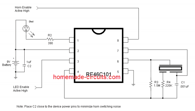
Basically we are talking about a single IC that is "integrated circuit" for those of you who are not total tech nerds – that can act like a warning system, complete with both a super annoying beeping sound and a flashing light. You know, just in case you are hard of hearing or visually impaired…sort of.
So picture this: you have some kind of sensor right? Maybe it is a smoke detector, or a moisture sensor, or something else that is keeping an eye on things. When that sensor detects something fishy, this little IC kicks into action, making a racket and flashing a light to get your attention.
How Does This Thing Actually Work?
Okay so the heart and soul of this whole circuit is a single chip – the RE46C101 from Microchip. It is like they crammed everything you need into one tiny little package.
This chip is seriously cool because it has a built-in driver specifically for piezos (we will get to those in a sec) and it has a circuit that is designed to flash an LED. It is like a two-for-one deal!
Now to power this whole operation, you just need a single 9-volt battery, the kind that looks like a little rectangle (a PP3 cell, if you want to get all technical about it). You hook that battery up to pins 2 and 5 on the chip, and it is ready to rock and roll.
Hooking Up the Piezo Thingy
Alright so what is a piezo? Well it is basically a little device that makes noise when you send electricity through it. Think of it like a tiny little speaker. This particular circuit needs a special kind of piezo transducer that has three pins, and you have got to make sure you connect it up correctly, just like in the picture.
Here is the breakdown:
The outer metal case of the piezo goes to pin #6.
The inner white part (the one that covers the most area) goes to pin #7.
And the smallest section of the piezo, right in the center, goes to pin #4, but it goes through a resistor first (that is the "R4" thing in the diagram).
If you hook it up right, the IC will blast out this super sharp, ear-piercing frequency through the piezo creating a warning sound that will make your hair stand on end.
Lights and Sounds together!
But wait, there is more! Not only does this IC make a super annoying noise but it also flashes an LED at the same time. The LED is connected to pin #1 on the chip and it will start blinking right along with the beeping sound. It is like a sensory overload of warning signals!
So how does all this magic happen? Well, the IC only starts beeping and flashing when it gets a "high logic" signal at pin #8. Think of it like a switch. When the switch is on, the IC does its thing. When the switch is off the IC stays quiet.
Putting It All Together
Now where does this "high logic" signal come from? That is where the sensor comes in. You hook up the sensor to pin #8 on the IC so that when the sensor detects something wrong, it sends that "high logic" signal to the IC, telling it to start beeping and flashing.
For example you could use this circuit in a smoke detector. When the smoke detector senses smoke or fire, it sends a signal to pin #8 on the IC which then starts blasting out a warning sound and flashing a light to alert you to the danger. It is a truly integrated system that can save lives!

Courtesy - ww1.microchip.com/downloads/en/DeviceDoc/22163A.pdf
Leave a Reply