For your upcoming Christmas decorating venture, are you trying to find a fundamental circuit for a 12 V LED string light flasher? Discover ways to construct an LED wig wag string light flasher with very few passive elements and a handful of transistors.
Blinking LED String Lights for Festivals
To make assembly easier, a schematic for an LED flasher has also been included.
You won't spend much money on this easy DIY project at home, but the end product will make you genuinely laugh.
Construct a basic LED flasher and figure out how to utilize it as décor. I assume you learnt how to utilize a modest voltage delivered to a transistor's base to toggle a load attached to the transistor's collector.
This straightforward LED wig wag flasher circuit is wired as a multivibrator using only a few transistors.
To create an eye-catching LED flashing effect, the transistors flip the LEDs linked to their collector points in turn. An LED warning flasher device may also be made using this circuit.
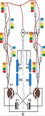
This transistor astable circuit might be set up in a variety of series and parallel connections, as seen in the graphic below.

Using the identical multivibrator flasher theory, the following graphic illustrates how series parallel LED string lights may be hooked to create a Christmas star or to decorate a tree.
Parts Required for the proposed LED flasher circuit using transistor AMV
| Component | Specification |
|---|---|
| Resistor (R1, R2) | 22K Ohm, 1/4 watt, 5% CFR (2 pieces) |
| Potentiometer | 47K Ohm (1 piece) |
| Resistor (LED Series) | 150 Ohm, 1/4 watt (as required for each LED) |
| LEDs (Random Colored) | 5mm, 40 pieces (random colored) |
| Capacitor (C1, C2) | 10 µF, 25V Electrolytic Radial (2 pieces) |
| Transistor (T2, T2) | BC547B (2 pieces) |
| General Purpose Board | Small piece, 4” x 4” (1 piece) |
This setup is for, a basic LED circuit, likely with multiple LEDs connected in series or parallel with appropriate resistors for current limiting. The potentiometer will allow you to adjust some aspect of the circuit (likely brightness or timing) and, the transistors will act as switching elements to control the LEDs. The capacitors may be used for filtering, or stabilizing the circuit while the generalpurpose board (veroboard or similar) will be used to mount and connect the components.
LED String Light using BJT AMV Concept?
Just a few easy steps are required to complete the building of this LED flasher, which is quite simple:
Place the two transistors in the board's middle, starting with the specified general purpose board.
Maintain a minimum of one inch of spacing between them.
Remove their leads neatly after soldering. After that, add capacitors and resistors to the board.
Once again, solder and use a nipper to snip their leads. Proceed to join their soldered leads as indicated by the circuit schematic.
The complete process shouldn't take longer than thirty minutes. The circuit board assembly is now complete.
Choose a plastic container that works well and drill the necessary holes in the exterior plate for the potentiometers.
As shown in the circuit diagram, insert the potentiometers into the corresponding slots and use flexible wires to link these to the appropriate locations on the circuit board.
LED Series Connections Details
Simply follow these steps to finish connecting the LED string:
You may read a thorough explanation of how to connect the LEDs in series and then parallel in one of my earlier posts.
Just adhere to the article's circuit instructions to finish building the two LED strings. On the other hand, you may just follow the LED connectors wiring schematic shown in this post.
In the end, you will discover that each of the LED strings have a shared positive and two negative points emerging out of them.
Testing Procedures
You can test the device in a few different ways with the aid of the included LED wig wag flasher schematic:
Solder the LED string outputs to the correct locations on the circuit board to form a connection.
When the circuit construction is finished and a 12 supply is connected, the entire LED string will begin to flash, creating the illusion of real fairy lights.
You may place this LED string light over your vehicle's wind shield in the right spot to make a charming small ornament.
To achieve even more incredible outcomes from the circuit, you may adjust the potentiometer settings to your preference.
Leave a Reply