The article describes the development of a homemade 10 watt LED lamp utilizing 10 to 12 numbers of 1 watt LEds.
In lots of earlier articles I mentioned the utilization of 1 watt white LEDs to create high effectiveness LED lamps for applying in homes for high bright, low usage lighting.
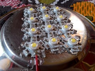
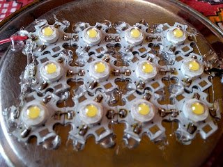
Right here we understand one more fascinating high watt LED lamp making use of 12nos of high bright 1 watt LEDs installed over a steel plate.
A regular $2 12V/1amp SMPS power supply was useful for driving it. Be aware of I have previously mentioned the construction of this SMPS circuit in one my prior content?
In spite of this in the suggested 10 watt LED circuit there are several severe specialized imperfections which ought to be repaired for making sure longevity to the lamp and for getting optimum outcomes from the unit.
The very first problem might be with the aid of steel material as the heasink. Of course we all realize that steel is not an effective conductor of heat, consequently it's certainly not suggested as a heatsink specifically for LEDs which are usually definitely delicate and susceptible to heat and current.
The rise in temperature within these LEDs could trigger making the devices to pull more current which may ultimately get changed into a run off circumstance and permanent harm to the LEDs or deteriorating of their lighting.
The above concern may be very easily discussed by including an aluminum plate rather than steel or iron. Size could possibly be just a few trial and error, it's always easier to choose a much bigger aluminum surface pertaining to the LED assembly dimension. Also make certain the plate is not heavier than 1mm, in fact the thinner the better, although not less than 0.5mm.
The above answer will certainly look after the heat dissipation of the LEDs, in spite of this if the ambient temperature gets warmer, as we generally encounter in tropical countries throughout summer time, the above alternative is probably not as much as necessary and can begin leading to issues.
For this purpose a good answer is to include a current limiter circuit in between the LED board and the SMP supply. This may limit the LEds from attracting current beyond the set safe limit regardless of the ambient temperature levelconditions.
I have previously taken care of an extremely helpful current limiter design in one y earlier articles, so we are able to include the same for the existing design.
In the prototype images demonstrated below we observe that the LEDs are organized in group of 4s, and the power supply utilized is 12V. According to the regular formula the arrangement is not going to need individual resistors, on the other hand since each LED could be obtaining only 12/4 = 3V,the luminosity could easily get somewhat lesser, simply because for maximum power a 3.3V is advisable for these LEDs.
You are able to once again refer to the circuit and the formulation introduced in the previously listed LED current controller circuit which demonstrates a configuration making use of 3 LEDs in the series with individual decreasing resistor.
The resistors carry out the function of publishing the current equally to the individual strings so that the lighting is uniformly provided across all the LEDs.


Leave a Reply