• Skip to main content
  • Skip to primary sidebar

Making Easy Circuits

Learn and build electronic circuits

You are here: Home / Car and Motorcycle Projects / Making Smart Car Turn-Signals, Side-Markers, and Parking Lights

Making Smart Car Turn-Signals, Side-Markers, and Parking Lights

Last Updated on February 17, 2018 by Admin Leave a Comment

The publish describes a smart circuit alteration that enables a single common lamp to be utilized as a parking light, turn signal indicator light, along with a side marker light on the appropriate positions.

In accordance with the very first necessity a single lamp needs to carry out the dual function of a turn signal lamp in addition to a park light, also the lamp ought to turn on the moment the turn signal switch is switched on.

The following altered smart turn signal cum park lamp performs the benefits precisely according to the above specifications.

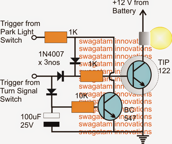
When the park light is in turned on position, the TIP122 switches ON the lamp by means of its base trigger via the upper diode and the series 1K resistor.

Currently, if the turn signal switch is activated, the TIP122 replies by flashing the lamp, while the lower BC547 transistor which also gets turned on with the turn signals ensures that the signal get from the park light switch is grounded and inhibited from affecting the lamp.

 
parklightcumturnsignallamp

Enhancing Car Turn Signal Lights, Park-Lights and Side-Marker Lights

The second necessity desires one more lamp which might be placed as a side marker lamp to react to the above side indicator or the turn signals but flash with an opposite switching. Also the same lamp is also expected to light up when the park lights are ON.

modifiedsidemarkerlampcircuit

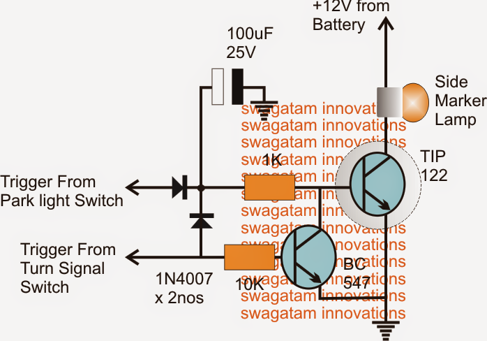
The diagram of the improved or the improved side marker lamp as demonstrated above fulfills the problems by flashing the linked lamp with reverse switching, as well as reacts to the park switch toggling throughout standard procedures.

The TIP122 is liable for initiating the lamp when the park lights are switch in.

In spite of this when the turn signal switch is toggled, regardless of the park light input the BC547 starts oscillating in accordance with the turn flash signals leading to the TIP122 to also blink the lamp with the associated flash rate.

The 100uF capacitor ensures that the TIP122 is given with its preserved positive feed for maintaining the lighting on the bulb in the course of the flashing behavior.

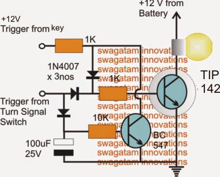
In accordance with the first diagram continues to be somewhat altered with the following handful of changes:

1) The transistor has become improved to TIP142.

2) The park-light input activate continues to be restored with +12V trigger from the ignition key so that the lamp works as fog lights and not as parking lights.

modifiedparklights

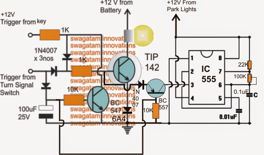
The above circuit could possibly be upgraded even more by introducing a PWM dimming control characteristic as demonstrated below. The characteristic allows dimming of the fog lights when the park lights are activated, however helps to ensure that the impact is inhibited the instant the turn signals are activated.

The 100k preset may very well be set properly for attaining the preferred decrease in the fog light luminosity


parklightwithPWM

You'll also like:

  • 1.  Variable Windscreen Wiper Delay Circuit
  • 2.  How to Make a Simple Motorcycle Security Alarm with Tilt Sensor
  • 3.  Automatic Day Night Triggered Car Headlamp Circuit
  • 4.  Garage Stop Light for Preventing Car Collision with Walls
  • 5.  DIY GSM Car Security Alarm Circuit
  • 6.  Brake Lights Monitor Circuit

About Admin

Hey friends, Thanks a bunch for stopping by this site! I am an engineer with a Bachelor of Engineering in Electronics and Telecommunication. One of my passions is gathering information from all sorts of electronics books and tutorials. I then take that information and compile it into a language that is super easy to understand. My goal is to make those complex electronics circuit concepts and technical terms much more accessible for all the new and budding electronics engineers out there. I can also design customized circuit diagrams as required by the users.
If you have any questions related to this field, please do not hesitate to drop a comment! I am always here and ready to help you out with any queries you might have. I cannot wait to hear from you!

Reader Interactions

Leave a Reply Cancel reply

Your email address will not be published. Required fields are marked *

Primary Sidebar

Categories

  • 3 Phase (4)
  • 8051 Microcontroller (1)
  • Arduino (11)
  • Audio and Amplifier (102)
  • Automation (8)
  • Battery Chargers (64)
  • Bicycle Projects (4)
  • Car and Motorcycle Projects (39)
  • Datasheets (10)
  • DIY Projects (5)
  • Electrical (15)
  • Free Energy (6)
  • Games Projects (2)
  • High Voltage (14)
  • Hobby Projects (30)
  • Household Circuits (2)
  • IC 555 Circuits (5)
  • Ignition Circuits (2)
  • Indicators (50)
  • Infrared (6)
  • Inverter Circuits (29)
  • Lights and Lamps (97)
  • Medical (8)
  • Meter and Tester Circuits (38)
  • Motor Driver (17)
  • New Circuits (56)
  • Oscillators (30)
  • Pets and Pests (5)
  • Power supply (80)
  • Protection Circuits (25)
  • PWM (9)
  • Remote Control (20)
  • Security and Alarm Circuit (48)
  • Sensors and Detectors (66)
  • Signal Processor (23)
  • Solar Controller Circuits (62)
  • SSR (3)
  • Temperature Controller (20)
  • Timer (25)
  • Transformerless (7)
  • Transmitters (12)
  • Tutorials (45)
  • UPS (2)
  • Voltage Regulators (57)
  • Water Sensor and Controller (29)
  • Home
  • Privacy Policy
  • Contact
  • Disclaimer
  • Copyright

© 2025 · Making Easy Circuits