• Skip to main content
  • Skip to primary sidebar

Making Easy Circuits

Learn and build electronic circuits

You are here: Home / Meter and Tester Circuits / Measure AC Millivolts using this Circuit

Measure AC Millivolts using this Circuit

Last Updated on November 17, 2024 by Admin Leave a Comment

In this piece, we examine a millivolt meter circuit built around an operational amplifier that is intended to precisely measure AC millivolts. Let's examine the specifics through the explanation that follows.

Measurements of DC potentials in the millivolt region could be made with the circuit below.

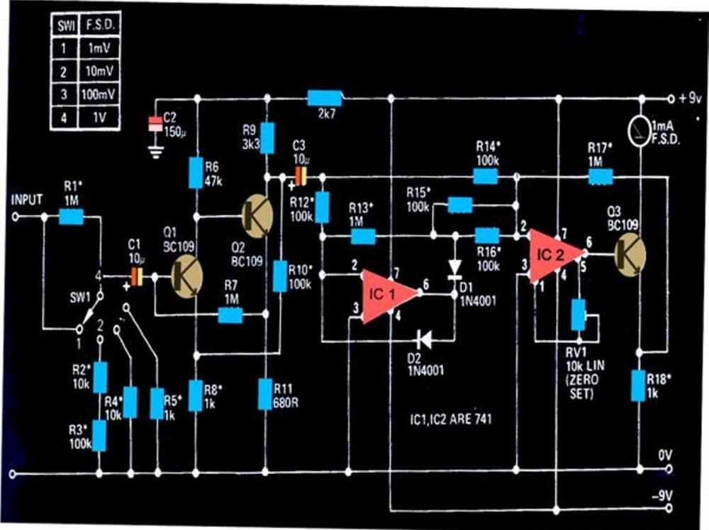
With a calibration range of 1 mV at the least and 1 V at the highest, the circuit is very sensitive.

Conventional multimeters typically have trouble detecting voltages in the millivolt range.

This circuit is capable of detecting extremely small AC impulses, down to 0.1 mV.

How the Circuit Works

Using the elements that are visible, the amplifier stage could be set to provide a gain of 100. The transistors Q1 and Q2 have been set as a high-gain feedback form of amplifier.

The couple of 741 ICs in the following stage, IC1 and IC2, have been configured as precision rectifiers.

When combined, they may produce a gain of ten throughout a possible bandwidth of over 50 kHz but less than 20 Hz.

Hence, the circuit's average gain is in the region of 1000, meaning that signals less than 1 mV must be well muted.

The AC millivolt meter circuit is simple to set up; all that has to be done at first is alter the preset RV1, which causes the attached meter to display a zero indicating that there is no signal at the input.

Every resistor with an asterisk (*) needs to be an MFR type with a 1% rating.

AC millivolt meter circuit diagram

You'll also like:

  • 1.  Temperature Meter Circuit using RTD
  • 2.  Simple LC Meter Circuit for measuring Inductance and Capacitance at Home
  • 3.  How to Build a 1.5 V Inductance Meter Circuit
  • 4.  Universal LED Bar Graph Indicator Circuit
  • 5.  Diode Matching Circuit (Pairing Circuit)
  • 6.  Simple Transistor Tester Circuit

About Admin

Hey friends, Thanks a bunch for stopping by this site! I am an engineer with a Bachelor of Engineering in Electronics and Telecommunication. One of my passions is gathering information from all sorts of electronics books and tutorials. I then take that information and compile it into a language that is super easy to understand. My goal is to make those complex electronics circuit concepts and technical terms much more accessible for all the new and budding electronics engineers out there. I can also design customized circuit diagrams as required by the users.
If you have any questions related to this field, please do not hesitate to drop a comment! I am always here and ready to help you out with any queries you might have. I cannot wait to hear from you!

Reader Interactions

Leave a Reply Cancel reply

Your email address will not be published. Required fields are marked *

Primary Sidebar

Categories

  • 3 Phase (4)
  • 8051 Microcontroller (1)
  • Arduino (11)
  • Audio and Amplifier (102)
  • Automation (8)
  • Battery Chargers (64)
  • Bicycle Projects (4)
  • Car and Motorcycle Projects (39)
  • Datasheets (10)
  • DIY Projects (5)
  • Electrical (15)
  • Free Energy (6)
  • Games Projects (2)
  • High Voltage (14)
  • Hobby Projects (30)
  • Household Circuits (2)
  • IC 555 Circuits (5)
  • Ignition Circuits (2)
  • Indicators (50)
  • Infrared (6)
  • Inverter Circuits (29)
  • Lights and Lamps (97)
  • Medical (8)
  • Meter and Tester Circuits (38)
  • Motor Driver (17)
  • New Circuits (56)
  • Oscillators (30)
  • Pets and Pests (5)
  • Power supply (80)
  • Protection Circuits (25)
  • PWM (9)
  • Remote Control (20)
  • Security and Alarm Circuit (48)
  • Sensors and Detectors (66)
  • Signal Processor (23)
  • Solar Controller Circuits (62)
  • SSR (3)
  • Temperature Controller (20)
  • Timer (25)
  • Transformerless (7)
  • Transmitters (12)
  • Tutorials (45)
  • UPS (2)
  • Voltage Regulators (57)
  • Water Sensor and Controller (29)
  • Home
  • Privacy Policy
  • Contact
  • Disclaimer
  • Copyright

© 2025 · Making Easy Circuits