• Skip to main content
  • Skip to primary sidebar

Making Easy Circuits

Learn and build electronic circuits

You are here: Home / Audio and Amplifier / Microphone Mixer Circuit

Microphone Mixer Circuit

Last Updated on November 24, 2018 by Admin Leave a Comment

Generally devices with a number of mic inputs is employed to create sound mixing through diverse sources. The proposed microphone mixer circuit has just been developed for a couple of microphone inputs. Nevertheless with exactly the same principle and it is possible to extend the amount of entries accessible for mixing. Within this model, both microphone inputs happen to be amplified and filtered prior to mixing the audio. In this manner, the losses associated with each input are reimbursed individually (via P1 and P2), and the noises is substantially minimized.

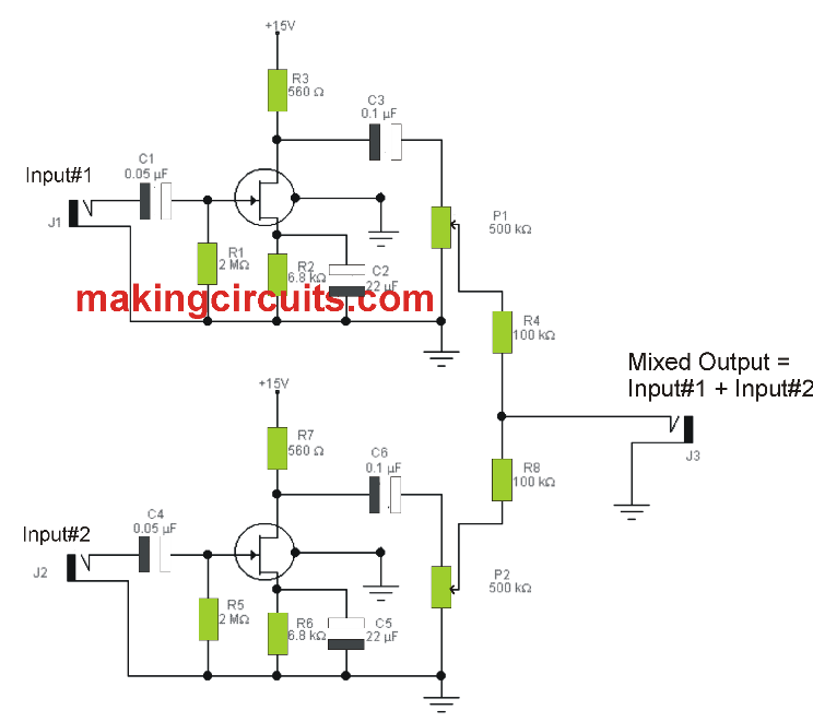
The utilization of FET transistors, that are known by their high input impedance, permits us to employ these preamplifier circuits with high impedance microphones for example glass and ceramics; using these you are able to achieve frequency response with no attenuation between 1Hz and 20KHz. Through the potentiometers P1 and P2 situated at the output of the preamplifiers, the volume of each of the microphones can be governed separately prior to mixing.

The power consumption of this circuit is very very low, just a few milliamps, and hence it really is well suited for portable equipment which is driven by batteries (for instance with a couple of 9V PP3).

Circuit Diagram

simple microphone mixer circuit

You'll also like:

  • 1.  2 Simple Electronic Gong Circuits Explained
  • 2.  Make this Booming Pistol Sound Simulator Circuit
  • 3.  DIY Guitar Jammer Circuit: Mix Tracks and Play Like a Pro
  • 4.  Guitar Effects Generator Circuit
  • 5.  How to make a Simple Music Box Circuit
  • 6.  Music Stroboscope Circuit

About Admin

Hey friends, Thanks a bunch for stopping by this site! I am an engineer with a Bachelor of Engineering in Electronics and Telecommunication. One of my passions is gathering information from all sorts of electronics books and tutorials. I then take that information and compile it into a language that is super easy to understand. My goal is to make those complex electronics circuit concepts and technical terms much more accessible for all the new and budding electronics engineers out there. I can also design customized circuit diagrams as required by the users.
If you have any questions related to this field, please do not hesitate to drop a comment! I am always here and ready to help you out with any queries you might have. I cannot wait to hear from you!

Reader Interactions

Leave a Reply Cancel reply

Your email address will not be published. Required fields are marked *

Primary Sidebar

Categories

  • 3 Phase (4)
  • 8051 Microcontroller (1)
  • Arduino (11)
  • Audio and Amplifier (102)
  • Automation (8)
  • Battery Chargers (64)
  • Bicycle Projects (4)
  • Car and Motorcycle Projects (39)
  • Datasheets (10)
  • DIY Projects (5)
  • Electrical (15)
  • Free Energy (6)
  • Games Projects (2)
  • High Voltage (14)
  • Hobby Projects (30)
  • Household Circuits (2)
  • IC 555 Circuits (5)
  • Ignition Circuits (2)
  • Indicators (50)
  • Infrared (6)
  • Inverter Circuits (29)
  • Lights and Lamps (97)
  • Medical (8)
  • Meter and Tester Circuits (38)
  • Motor Driver (17)
  • New Circuits (56)
  • Oscillators (30)
  • Pets and Pests (5)
  • Power supply (80)
  • Protection Circuits (25)
  • PWM (9)
  • Remote Control (20)
  • Security and Alarm Circuit (48)
  • Sensors and Detectors (66)
  • Signal Processor (23)
  • Solar Controller Circuits (62)
  • SSR (3)
  • Temperature Controller (20)
  • Timer (25)
  • Transformerless (7)
  • Transmitters (12)
  • Tutorials (45)
  • UPS (2)
  • Voltage Regulators (57)
  • Water Sensor and Controller (29)
  • Home
  • Privacy Policy
  • Contact
  • Disclaimer
  • Copyright

© 2025 · Making Easy Circuits