This music operated dancing light circuit can be positioned in front or near any loudspeaker or an audio source and enable a correspondingly dancing or sequencing lights connected at the output of the circuit.
Since the design is based on triacs and mains AC, the lamps are 220V or 120V AC filament lamps, which may be colored for enhancing the disco effect on them.
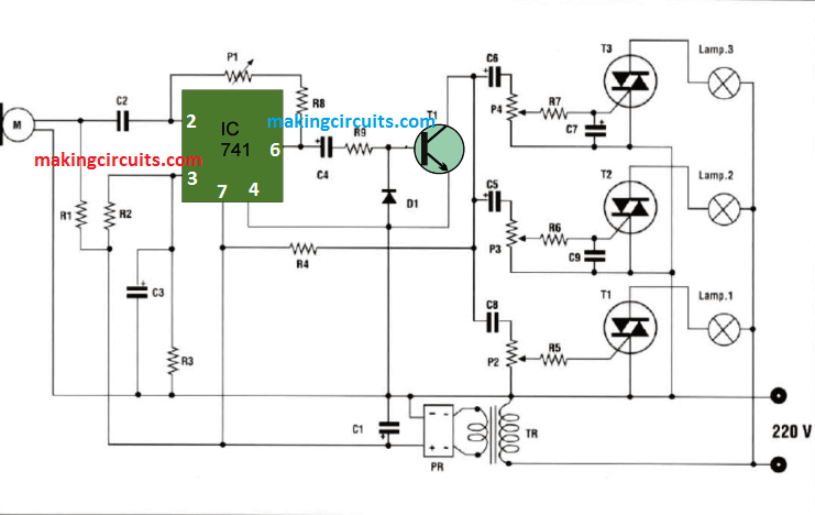
The compete schematic of the proposed music light circuit can be seen below:
Circuit Description:
The circuit functioning can be understood from the following points:
We can see a MIC at the left hand side, a 741 IC stage at the center configured as a comparator, and 3 triacs with lamps on the right side.
The power to the circuit is applied from a transformer based power supply circuit, and also AC mains for the 20V bulbs or lamps.
Without any sound signal on the MIC all the lamps are in the switched OFF mode because pin#2 of the IC 741 is held low causing pin#3 to be high, and this forces its output pin#6 also to be high, which in turn causes the NPN T1 to conduct and keep the triac gates connected with ground. Due o this all the triacs remains shut off.
However when a suitably powerful sound signal may be from a loudspeaker hits the MIC, the MIC resistance starts fluctuating room low to high and vice versa, in response to the sound pressure of the music.
This fluctuating pulses correspondingly causes the output of the IC 741 also to fluctuate, and this in turn forces the triac gates to switch ON OFF in tandem and quite in a sequential manner, enabling a dancing or chasing kind of light effect illumination on the connected lamps.
In fact, all the triacs are switched at the same rate however due to the the presets at the gates of the respective triacs, the switching timing can be slightly changed enabling a running or chasing kind of sequential lighting effect on the lamps in response to the music from the source.
The degree at which the different triacs can be fired is adjusted by the respective presets, enabling a beautiful music light operation on the lamps without any physical contact with the music source.
However be extremely cautious not to touch the internal circuit of the design while it is in the powered state because the whole circuit is not isolated from mains and therefore might e floating at the mains level.
If you have any doubt regarding the making of the above music light circuit without wire and contact, you can use the comment box below for expressing the same.
Parts List
T1 = 4A400VTRIAC
T2-4A400VTR1AC
T3 = 4A400VTRIAC
Q1 = 2N2218
IC1 = 741
R1 = 22 K
R2 = 47 K
R3 = 47 K
R4 = 330
R5 = 330
R6 = 330
R7 = 330
R8 = 150 K
R9= 100
P4 = 2,2 Kohms pot
Cl = 220 uF16Velec.
C2 = 22 nF ceramic.
C3 = 10uF16V elec.
C4=10 uF16V elec.
C5=1 uF16V elec.
C6=1 uF16V elec.
C7=1uF16V elec.
C8 = 330 nF pol.
C9= 100 nF ceramic.
D1 = 1N4148
PR= Bridge
PI = 2.2 Mpot
P2 = 2.2 K pot
P3 = 2.2 K pot
M = capsule mic
TR = transfo 230/9 V 0,25A
PCB design for the music light circuit

hi,
the famous and every-place-available transistors bc107, c945,c1815 or c828 can do the job as well.
yes will do….
Hi, what transistor can i use in place of the 2N2218
2N2222