• Skip to main content
  • Skip to primary sidebar

Making Easy Circuits

Learn and build electronic circuits

You are here: Home / Inverter Circuits / No Load Detection Shut Down for Inverters

No Load Detection Shut Down for Inverters

Last Updated on February 27, 2019 by Admin 5 Comments

The write-up examines a relay cut-off circuit which is often installed into inverters in order to makes sure a no load detection, shut down for inverters immediately implemented stopping the inverter from working without need.

The discussed theory refers to a problem in which a no load condition is expected to be discovered and cut-off from continuing, that is we explore a circuit pertaining to protecting against a no load condition for inverters.

No Load Detection and Shut Down for Inverters

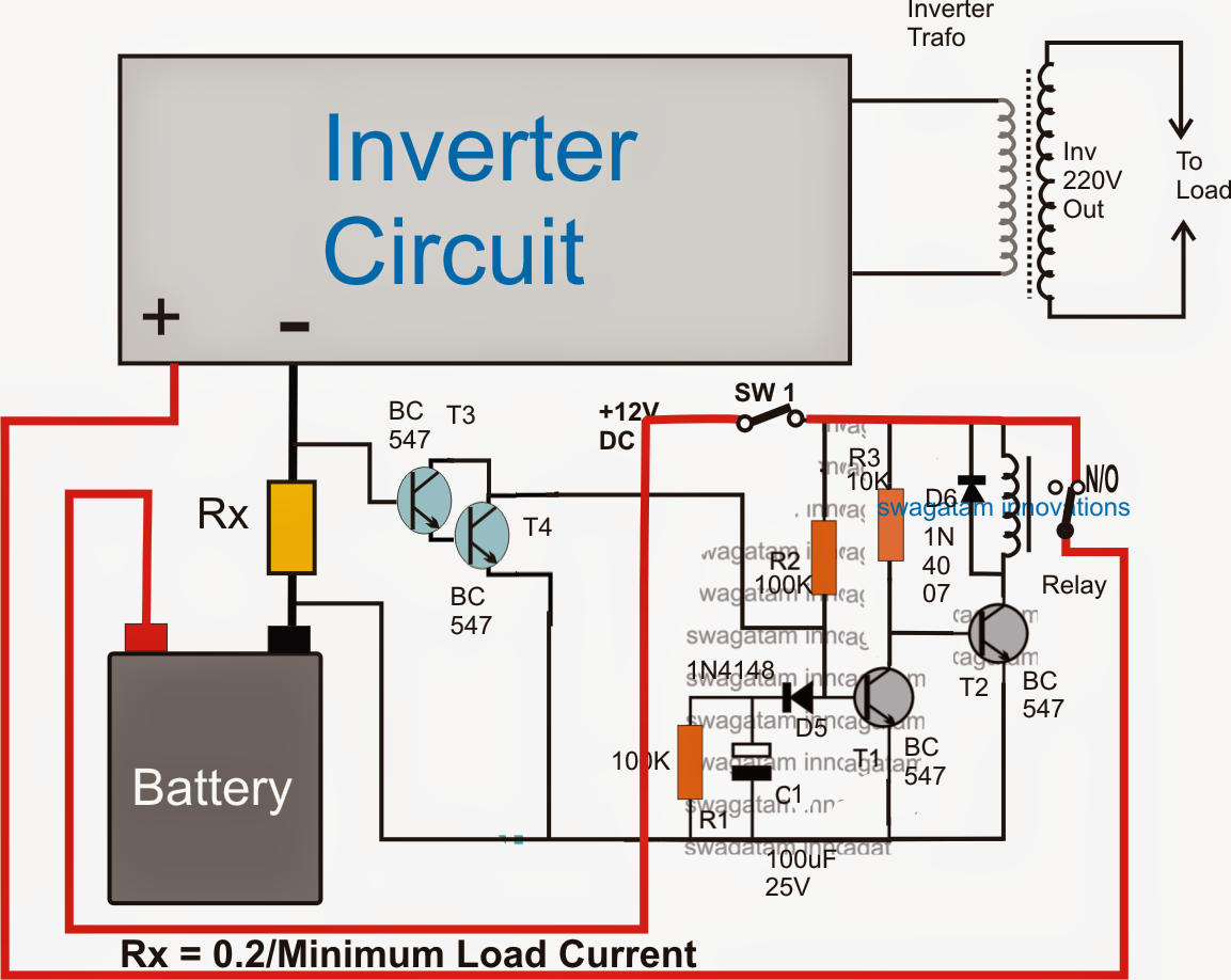
As displayed in the above image, a no load detector and cut of technique could be opened up by using this layout in any inverter circuit.

The functional specifics could be comprehended with the following description:

The circuit includes two stage, particularly the current amplifier and sensor stage making use of the T3/T4 Darlington pair, along with a basic delay ON timer stage employing T1, T2 and the involved parts.

When SW1 is started up, the delay-ON timer is started via C1 which will start charging through R2 and D5 trying to keep T1 turned off in the operation. With T1 switched off, T2 is switched ON which as a result switches ON the relay.

The relay helps the positive from the battery to get linked with the inverter in order that the inverter is capable of start up and produce the specified AC mains into the desired home equipment.

Considering the existence of a load within the output the battery experiences a symmetrical sum of current intake, and in the process Rx encounters a current circulation through it.

This current is changed into an equivalent quantity of voltage around Rx that is detected by the T3/T4 Darlington pair and it is pushed to switch ON.

Having T3/T4 started up, C1 will be immediately stopped from becoming charged, leading to an instant deactivating of the delay ON timer, ensuring the output of the inverter never stops the supply of the voltage to the load.

On the other hand, imagine the output of the inverter is lacking virtually any load (no load condition), T3/T4 may be then struggling to activate, that enables C1 to acquire charge steadily so that the potential around it can be ample to activate T1.

The moment T1 is activated, T2 will be blocked and thus will be the relay. Considering the relay contacts cut-off and changed from N/O to the N/C contact, the positive for the inverter is likewise cut-off, the device reaches a stand still.

You'll also like:

  • 1.  Simple Sinewave Inverter Circuits
  • 2.  Build this 3 Phase Inverter Circuit with Arduino: Full Program Code
  • 3.  How to Convert 12 V to 19 V using Boost Converter Circuit
  • 4.  12V to 120V Inverter Circuit
  • 5.  3 Easy SG3525 Inverter Circuits Explored
  • 6.  7 Simple Inverter Circuits for Newcomers

About Admin

Hey friends, Thanks a bunch for stopping by this site! I am an engineer with a Bachelor of Engineering in Electronics and Telecommunication. One of my passions is gathering information from all sorts of electronics books and tutorials. I then take that information and compile it into a language that is super easy to understand. My goal is to make those complex electronics circuit concepts and technical terms much more accessible for all the new and budding electronics engineers out there. I can also design customized circuit diagrams as required by the users.
If you have any questions related to this field, please do not hesitate to drop a comment! I am always here and ready to help you out with any queries you might have. I cannot wait to hear from you!

Reader Interactions

Comments

  1. BIPRENDU PRAMANICK says

    June 20, 2024 at 10:25 pm

    what is the value of the RX on your circuit

    Reply
    • admin says

      June 26, 2024 at 9:08 am

      The formula for calculating RX is given in the circuit diagram, please check it….

      Reply
  2. pacifique says

    March 11, 2016 at 12:44 am

    i want to make static transfer switch circuit which will have two 12v dc power sources and able to switch the the second source whenever the priority source fails in no more than milliseconds so plz help me

    Reply
    • admin says

      March 12, 2016 at 2:03 pm

      just Google “router modem DC ups circuit”…you will get the required circuit in the results

      Reply
  3. pacifique says

    March 11, 2016 at 12:37 am

    hello, i thank you for a good circuit you published so i would like to make this circuit able too detect back the load and switch on when it is reconnected. so how can i modify the circuit? thanks in advance

    Reply

Leave a Reply Cancel reply

Your email address will not be published. Required fields are marked *

Primary Sidebar

Categories

  • 3 Phase (4)
  • 8051 Microcontroller (1)
  • Arduino (11)
  • Audio and Amplifier (102)
  • Automation (8)
  • Battery Chargers (64)
  • Bicycle Projects (4)
  • Car and Motorcycle Projects (39)
  • Datasheets (10)
  • DIY Projects (5)
  • Electrical (15)
  • Free Energy (6)
  • Games Projects (2)
  • High Voltage (14)
  • Hobby Projects (30)
  • Household Circuits (2)
  • IC 555 Circuits (4)
  • Ignition Circuits (2)
  • Indicators (50)
  • Infrared (6)
  • Inverter Circuits (29)
  • Lights and Lamps (97)
  • Medical (8)
  • Meter and Tester Circuits (38)
  • Motor Driver (17)
  • New Circuits (56)
  • Oscillators (30)
  • Pets and Pests (5)
  • Power supply (81)
  • Protection Circuits (25)
  • PWM (8)
  • Remote Control (20)
  • Security and Alarm Circuit (48)
  • Sensors and Detectors (66)
  • Signal Processor (23)
  • Solar Controller Circuits (61)
  • SSR (3)
  • Temperature Controller (20)
  • Timer (25)
  • Transformerless (7)
  • Transmitters (12)
  • Tutorials (45)
  • UPS (2)
  • Voltage Regulators (57)
  • Water Sensor and Controller (29)
  • Home
  • Privacy Policy
  • Contact
  • Disclaimer
  • Copyright

© 2025 · Making Easy Circuits