The submit describes a call bell network system for office complexes which might be employed for contacting and tracking office member's attendance and reply from the specific meant office chamber.
The suggested office call bell network as required above might be summarized provided below:
The central head office ought to be attached to each of the office departments such that pressing the specific push buttons rings the related bell in the preferred office chamber.
In an event the concerned office member is not in the "called" office, but in other sorts of close by department and hears the ringing, has the capacity to react by showing up at the "answer button" from the other office the member could be located throughout that immediate.
The above reply gets kept in the form a glowing LED in the head office enabling the attendant there to check the concerned members exact position.
The circuit achievement of the offered office call bell monitor network can be achieved by utilizing several set/reset flipflops as might be observed below diagram:
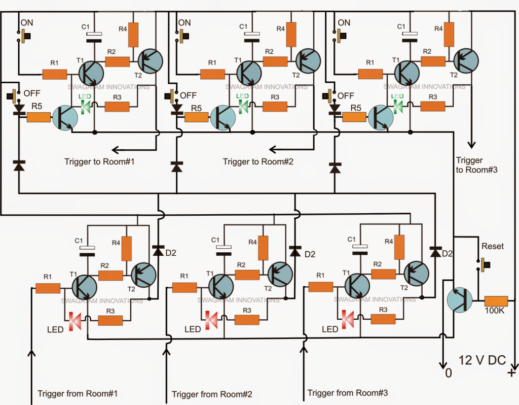
The circuit above demonstrates an illustration wiring for three office rooms which can be lengthy to any most wanted numbers basically replicating the stages.
As may be seen the upper section comprises three identical stages of transistor set/reset modules, each module being made up of two NPN transistors, one PNP, a couple push buttons and a few resistors.
The push button labeled as "ON" is utilized for signaling or provoking the latch circuit comprised of T1 and T2. The OFF button does the reverse that is deactivates the certain module activation.
When started a positive voltage turns into offered at the collector the corresponding PNP transistor which can be shut down for activating the office bell located at the specific office, in the diagram these are labelled as "Trigger to room#1, room#2, room#3...."
When one of these triggers is started it's presented to a relay driver circuit system set up in the intended office chamber where the trigger is provided to the base of the relay driver transistor as demonstrated in the diagram below (labelled as "trigger from head office").
This encourages the relay to get initialized as well as the linked bell across the relay contacts.
The member now presses the green switch in result which happens to be moved back to the head office and gathered across one of the inputs marked "trigger from room#1, room#2 room#3..." relying upon from where the member might have attended the green button. This activity allows an immediate switching off of the bell.
If it was from the concerned room, say as an example room#1 then the corresponding red LED placed in "room#1"module gets lighted and latched, if it was from any other room the corresponding red LED is activated offering the right immediate location of the member in the course of his/her reaction to the call made from the head office.
The red LED illumination could be reset and restored to its turned OFF position by pressing the reset button at the extreme right corner of the above head office call bell monitor circuit above.

Parts list
All R1 = 100 k
All R2, R3, R4 = 10 K
All diodes = 1N4148
All C1 = 100uF/25V
All NPN = BC547
All PNP = BC557
Leave a Reply