In this post we learn about an automatic programmable 7 day plant watering system circuit as requested by Mr. Michael.
Here's the requested as given in the below paragraph
Hello admin,
The timing circuit must be powered with 9v and its function will be to switch on and off a 9v supply to a microcontroller circuit at programmed intervals once every one, two, three ….. up to seven days through a trimpot marked 1-7.
The circuit must switch off after 20 secs.
The time delay of the first (and subsequent) switch-ons should also be programmed through a trimpot marked 1-12 (hours) and a “SET” button.
The whole philosophy is the same with some automatic watering programmers (no screen or real time needed).
Thanks, Michael
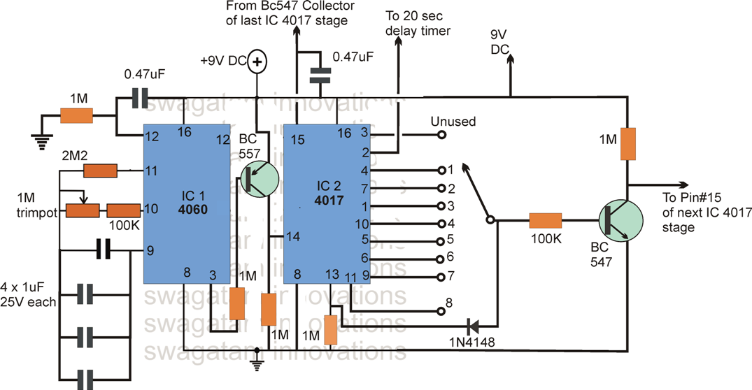
The automatic plant watering timer circuit can be visualized in the above images. The description can be understood from the following explanation:
1) IC 4060 is wired as a standard timer circuit which generates clock signals at a rate depending on values of the R, C components connected across its pin#9 and pin#10. This could be set to achieve a clicks signals with delays of 1 hour, 2 hour or whatever may be required to appear at pin#3 of the IC. Only one of the 7 stages are shown above, for 7 days week you will have to make 7 nos of IC 4017 stage...the 4060 need not be repeated, the signal from pin#3 and BC557 of IC 4060 can be commonly applied to all the 4017 stages.
3) THe above clocks are transferred to pin#14 of IC 4017 via the BC557 transistor.
4) Te IC4017 responds to each positive edged clocks and shifts a logic high across its pin#3 to pin#8
5) The selector switch across the 4017 outputs decides after how many hours the next similar stage needs to be triggered so that the next 4017 stage repeats the timing cycle, and subsequently the next second 4017 stage triggers the 3rd 4017 stage through its own selector switch and the BC547 stage....and so on.
The 20 second Delay Timer circuit for the programmable plant watering timer circuit
Pin#2 of the IC 4017 can be connected to a 20 second delay OFF timer circuit, which can be built as per the below given diagram. Pin#2 of the 4017 IC is configured with the 33uF end of the following circuit.

When power is first switched ON, the IC 4017 and 4060 both get reset, and simultaneously the logic from pin#3 of 4017 jumps to its pin#2.
This initiates the 20 second timer circuit by triggering its relay ON.
The relay now powers the MCU...but only until 20 seconds have elapsed, when the timer switches OFF the relay ans the MCU.
After this the IC 4060 keeps counting and with every logic high clock it forces the IC 4017 to shift its logic across the shown output pinouts.
Depending on which pinout is connected with the selector switch the 4017 C latches and halts when the logic shifts on that particular pinout.
Once this happens , the BC547 carries forward the process and triggers the next 4017 IC, and the same process is repeated with the second stage until the 3rd stages is trigger and s on.
Modified water timer diagram as per the rectifications suggested by Mr. Michael:
Please refer to the comment discussion for the details.
Leave a Reply