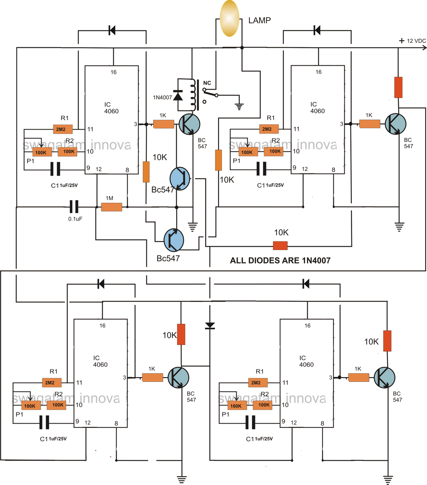
This circuit of a flexible programmable timer circuit spelled out in this post was created by me. Let's get more information about the request and the circuit details.
So here's the circuit that I invented for Programmable Timer Circuit for Fish Aquarium. As the term advise, the timer is rather adaptable and might be modified to generate any preferred time periods, based on the above asked for format.
The circuit contains four similar phases, comprised of the IC 4060 timer configuration. The timer series starts from the IC at the top left corner.
When power is turned on this IC begins counting. Based upon the setting of its pot, the IC generates after a specific period og time interval.
This switches ON the relay and the driver transistor BC547 which as a result switches OFF the hooked up lamp. The phase obtains latched with the aid of the diode linked across its pin 3 and pin 11.
The above initiating also switches yet another BC547 transistor which hooks up the reset pin of the next IC 4060 to ground which is linked to this phase also. After a specific time, this IC also causes its output at pin3 and gets latched by the corresponding diode, however this actionsends a comments signal to the relay driver transistor, immediately switching it off and restoring power back to the lamp so that it lights up again.
Just as the above methods, the series even more continues and turns ON the third IC 4060 in the line which counts the set time interval and pulls the relay back to OFF position via the diode linked to the collector of its bc547 transistor, such that the lamp again gets turned OFF.
The moment the above initiating occurs the last section at the bottom right corner switches into action and counts as per the setting of the specific pot, until the ICs output turns into high, this high reset the the first IC and switches ON the lamp once again to ensure that the procedure might be restart the cycle from the beginning.

The pots might be improved to 3m3 for producing higher time interval periods, so is true with the specific capacitors.
The Programmable Timer Circuit for Fish Aquarium might be modified as per the delivered request, in the following manner:
If we think about the first timing sequence to commence at 7am and end at 12pm, means the upper left timer's P1 ought to be modified such that it triggers the relay and switches off the relay after precisely 5 hours.
For maintaining the lamp turned OFF in the above position and switch it ON back at 6 pm we right now adjust P1 of the upper right timer section such that its output generates after another 5 hours. This switches ON the lamp again.
The above circumstance ought to be held unaffected until night 10pm, which is about 4 hours of period, for that reason we adjust the lower right timer's P1 to get it activated after 4 hours of time interval.
Ultimately, for beginning the above process back again the next morning at 7am, P1 of the last timer at the lower right is realigned such that it resets the first timer after 9 hours..... and the cycle repeats.
For creating the circuit operate based on the above stipulated timing structure, after modifying the specific hours, the unit ought to be run or turned on precisely at 7 clock in the morning....rest will immediately carry out.
Leave a Reply