Several electrical resistances could be hooked up both in series or in parallel, likewise, in excess of 2 resistances may also be joined in groups of series and parallel each. In this article we are going to primarily talk about series and parallel resistance combination.
Resistances in Series
Assume there are, 3 resistors, R1, R2 and R3 and we add them by their end terminals as displayed in the image below, then this could be called resistances in series. In such a series relationship, the equivalent resistance resulting from the collaboration, will be the total of these three electrical resistances.
That signifies, resistance between point A and D in the figure below, is corresponding to the sum of 3 individual resistances. The current getting into from the point A of the set up, will likewise go out from point D since we do not have any other parallel route offered in the circuit.
Then let's assume this current is I. Which means this current I is going to move across the resistance R1, R2 and R3. Making use of Ohm’s law, we are able to deduce that voltage drops occurring across the resistances are going to be V1 = IR1, V2 = IR2 and V3 = IR3.
Now, if the overall voltage switched ON over the combined resistances in series, is V.
Then naturally we will have:
V = IR1 + IR2 + IR3---------(1)

It is evident from above that the sum of voltage drops across the individual resistance is simply equal to voltage applied across the series assembly.
Therefore, imagining the whole combination of resistances like a single resistor having an electric resistance of value R, then applying Ohm’s law to this gives,V = IR ………….(2)


From the above equation it becomes evident that when resistances are joined in series, their combined value or the total value becomes equal to the sum of the values of the individual resistances. Now, instead of just 3 resistors if we imagine the total number of the resistances in the series to be n numbers of resistances, then the resultant equivalent resistance can be calculated as:R = R1 + R2+ R3+.......Rn
Resistances in Parallel
Let’s consider three resistors having resistance values as R1, R2 and R3 are connected in a way, that their all the right side terminals of each resistor are joined with each other, and identically the left side terminals of each resistor are also soldered with each other, as shown below:
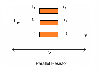
When resistors are connected in this way, the assembly is called resistances in parallel. If a voltage difference is connected across this combination, the assembly will begin drawing a specified amount of current, let's say I.
Since the current would come across 3 parallel routes through the resistors, the current would be eventually divided into 3 distinct sections. Let's names them as currents I1, I2, and I3 moving across the resistors R1, R2, and R3 respectively, wherein the sum of the all the current will be equal to the source current, as indicated below:
I = I1 + I2 + I3
From the figure above we can understand that since the common ends of the resistors are all connected to a common voltage source, the drop in voltage across each of the resistors has to be uniform, and equal to the value of the supply voltage source.
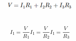
Therefore by applying Ohm's law we get:
Finding the Equivalent Resistance in a Parallel Combination
Now, if we take an equivalent value for all the resistance as R and the equivalent value of the current as I, we get the following basic expression:I = V/R
If we replace this value of I in our first equation (1), we derive the following relationships:
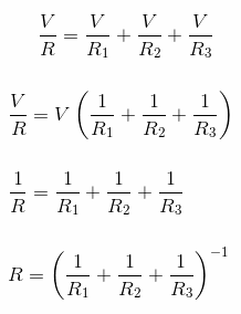
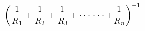
The last expression above gives us the formula for calculating the equivalent resistor value in a parallel resistor circuit. If we imagine n number of parallel resistors in a network, the formula for calculating the equivalent resistance could be expressed as given below:
Leave a Reply