• Skip to main content
  • Skip to primary sidebar

Making Easy Circuits

Learn and build electronic circuits

You are here: Home / Tutorials / How Resistors Work With AC Supply

How Resistors Work With AC Supply

Last Updated on February 17, 2018 by Admin Leave a Comment

In this post we learn how resistors work and behave in alternating current (AC) driven circuits

AC resistor circuits

02053

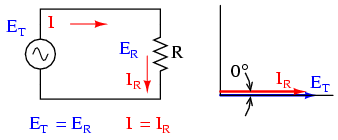
Genuine resistive AC circuit: resistor voltage and current tend to be in phase.

In case we were to draw the graph for the current and voltage for any simple AC circuit comprising a supply source along with a resistor (image above), it may well appear quite the way it's show here: (Figure below)

02054 1

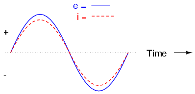
Voltage and current “in phase” for resistive circuit.

Due to the fact the resistor basically and specifically restricts the stream of electrons at all time frames, the waveform for that voltage drop over the resistor is precisely in phase with the waveform for that current circulating within it.

We are able to examine just about any moment in time across the horizontal axis of the graph waveform plot and evaluate those magnitudes of current and voltage with one another (any “snapshot” view for the values of a waveform are known as instantaneous values, indicating the values at that instantaneous moment in time).

Once the instantaneous value regarding current is 0 %, the instantaneous voltage over the resistor can also be 0 %.

In the same way, in any instant on time in which the current via the resistor reaches its positive maximum, the voltage over the resistor is additionally in its positive maximum, and so forth. At virtually any assigned position on time across the waveform, Ohm's Law is valid for those instantaneous values of voltage and current.

We are able to likewise determine the power dissipated through this resistor in a AC circuit, and plot all those values on a single graph: (Figure below)

02055


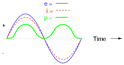
Instantaneous AC power within a real resistive circuit is often positive.

Remember that the power will certainly not be a negative value. Once the current is positive (over a range), the voltage can also be positive, producing power (p=ie) of a positive magnitude.

Alternatively, once the current is negative (under the range), the voltage can also be negative, resulting in a positive number for power (a minus quantity multiplied by a new minus quantity equates to a positive quantity).

This specific steady “polarity” of power informs us how the resistor is usually dissipating power, getting it with the supply and releasing it by means of heat power. Regardless of if the current is positive or negative, a resistor never stops dissipating energy.

You'll also like:

  • 1.  Semiconductor Diodes – Internal Structure and Working Explained
  • 2.  How to Calculate Voltage Drop
  • 3.  Resistivity and Laws of Resistance
  • 4.  How to Calculate Timer Circuits using CMOS Gates
  • 5.  Basic Electrical Definitions, Concepts, Formulas and Equations
  • 6.  How Voltage Dividers Work

About Admin

Hey friends, Thanks a bunch for stopping by this site! I am an engineer with a Bachelor of Engineering in Electronics and Telecommunication. One of my passions is gathering information from all sorts of electronics books and tutorials. I then take that information and compile it into a language that is super easy to understand. My goal is to make those complex electronics circuit concepts and technical terms much more accessible for all the new and budding electronics engineers out there. I can also design customized circuit diagrams as required by the users.
If you have any questions related to this field, please do not hesitate to drop a comment! I am always here and ready to help you out with any queries you might have. I cannot wait to hear from you!

Reader Interactions

Leave a Reply Cancel reply

Your email address will not be published. Required fields are marked *

Primary Sidebar

Categories

  • 3 Phase (4)
  • 8051 Microcontroller (1)
  • Arduino (11)
  • Audio and Amplifier (102)
  • Automation (8)
  • Battery Chargers (64)
  • Bicycle Projects (4)
  • Car and Motorcycle Projects (39)
  • Datasheets (10)
  • DIY Projects (5)
  • Electrical (15)
  • Free Energy (6)
  • Games Projects (2)
  • High Voltage (14)
  • Hobby Projects (30)
  • Household Circuits (2)
  • IC 555 Circuits (5)
  • Ignition Circuits (2)
  • Indicators (50)
  • Infrared (6)
  • Inverter Circuits (29)
  • Lights and Lamps (97)
  • Medical (8)
  • Meter and Tester Circuits (38)
  • Motor Driver (17)
  • New Circuits (56)
  • Oscillators (30)
  • Pets and Pests (5)
  • Power supply (80)
  • Protection Circuits (25)
  • PWM (9)
  • Remote Control (20)
  • Security and Alarm Circuit (48)
  • Sensors and Detectors (66)
  • Signal Processor (23)
  • Solar Controller Circuits (62)
  • SSR (3)
  • Temperature Controller (20)
  • Timer (25)
  • Transformerless (7)
  • Transmitters (12)
  • Tutorials (45)
  • UPS (2)
  • Voltage Regulators (57)
  • Water Sensor and Controller (29)
  • Home
  • Privacy Policy
  • Contact
  • Disclaimer
  • Copyright

© 2025 · Making Easy Circuits