• Skip to main content
  • Skip to primary sidebar

Making Easy Circuits

Learn and build electronic circuits

You are here: Home / Audio and Amplifier / Scratch And Rumble Filter Circuit

Scratch And Rumble Filter Circuit

Last Updated on June 26, 2020 by Admin Leave a Comment

Scratch and rumble filtering circuit is a important element in a hi fi amplifier, however is definitely one which can be lacking through several layouts, or if this filtering exists this could have the form of a somewhat inadequate 6dB per octave sort filter.

This kind of circuit is a 12dB per octave add-on scratch and rumble filter which is often linked into the tape monitor or any comparable facility of the amplifier.

Scratch And Rumble Filter Circuit can be a standard second order filter circuit possessing passive high pass filter created through the series capacitance C3 and C4, as well as the parallel resistance of R2 and R3 (the latter furthermore being utilized to bias emitter follower transistor Q1).

fig1 30

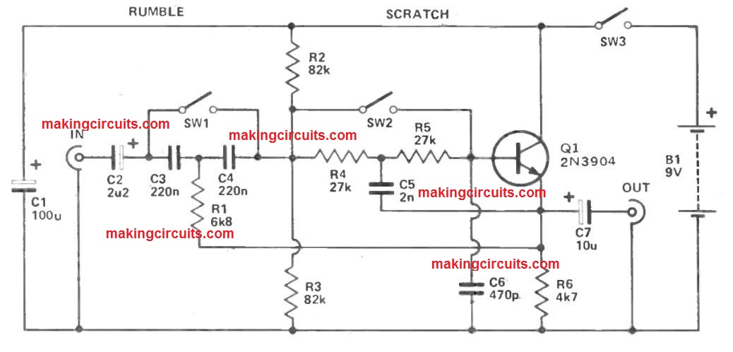
A passive filter of this form provides just a very sluggish initial roll off, and an best attenuation rate of just 6dB per octave. A bootstrapping resistor is as a result employed to enhance efficiency.

Over a cutoff frequency in which the gain of the circuit might or else decline fairly, R1 has got the a result of reinforcing the input signal through the output of the buffer amplifier depending on Q1.

Properly under the cut off frequency, losses via C4 result in the signal level at Q1 emitter being good below that at the junction of C3 and C4. This leads to a few of the signal at the junction of C3 and C4 being tapped off via R1, with C3 and R1 efficiently developing a second high pass filter network.

This gets rid of the gradual initial roll off rate (actually there exists a small and minor peak of around 0.5dB over a cut off frequency) and increases the attenuation rate to a minimal 12dB per octave.

The low pass filter functions in very similar way as the high pass one, except certainly, the R and C filter elements happen to be transposed in order to provide the right filter action.

If perhaps low pass filtering is needed, SW1 works extremely well successfully to bypass the high pass filter elements. C2 then preserves DC obstructing at the input.

SW2 may be used to bypass the low pass filter components when just high pass filtering is essential.

Using the particular part values the rumble filter response drops beneath unity at around 45Hz, extends to the -6 dB point merely above 30Hz, and after that drops away at a nominal 12dB per octave.

The scratch filter response crosses the unity gain point at around 6.5kHz, gets to the -6dB point at around 10kHz, and after that drops away at a minimal 12dB per octave

You'll also like:

  • 1.  Best Active CrossOver Filter Circuit for Speaker Boxes
  • 2.  250 Watt MOSFET Power Amplifier Circuit
  • 3.  Designing a MOSFET Power Amplifier Circuit
  • 4.  Simple Microphone (MIC) Amplifier Circuits
  • 5.  Simple Dual Tone Siren Circuit
  • 6.  Electronic Bongo Circuit

About Admin

Hey friends, Thanks a bunch for stopping by this site! I am an engineer with a Bachelor of Engineering in Electronics and Telecommunication. One of my passions is gathering information from all sorts of electronics books and tutorials. I then take that information and compile it into a language that is super easy to understand. My goal is to make those complex electronics circuit concepts and technical terms much more accessible for all the new and budding electronics engineers out there. I can also design customized circuit diagrams as required by the users.
If you have any questions related to this field, please do not hesitate to drop a comment! I am always here and ready to help you out with any queries you might have. I cannot wait to hear from you!

Reader Interactions

Leave a Reply Cancel reply

Your email address will not be published. Required fields are marked *

Primary Sidebar

Categories

  • 3 Phase (4)
  • 8051 Microcontroller (1)
  • Arduino (11)
  • Audio and Amplifier (102)
  • Automation (8)
  • Battery Chargers (64)
  • Bicycle Projects (4)
  • Car and Motorcycle Projects (39)
  • Datasheets (10)
  • DIY Projects (5)
  • Electrical (15)
  • Free Energy (6)
  • Games Projects (2)
  • High Voltage (14)
  • Hobby Projects (30)
  • Household Circuits (2)
  • IC 555 Circuits (5)
  • Ignition Circuits (2)
  • Indicators (50)
  • Infrared (6)
  • Inverter Circuits (29)
  • Lights and Lamps (97)
  • Medical (8)
  • Meter and Tester Circuits (38)
  • Motor Driver (17)
  • New Circuits (56)
  • Oscillators (30)
  • Pets and Pests (5)
  • Power supply (80)
  • Protection Circuits (25)
  • PWM (9)
  • Remote Control (20)
  • Security and Alarm Circuit (48)
  • Sensors and Detectors (66)
  • Signal Processor (23)
  • Solar Controller Circuits (62)
  • SSR (3)
  • Temperature Controller (20)
  • Timer (25)
  • Transformerless (7)
  • Transmitters (12)
  • Tutorials (45)
  • UPS (2)
  • Voltage Regulators (57)
  • Water Sensor and Controller (29)
  • Home
  • Privacy Policy
  • Contact
  • Disclaimer
  • Copyright

© 2025 · Making Easy Circuits