• Skip to main content
  • Skip to primary sidebar

Making Easy Circuits

Learn and build electronic circuits

You are here: Home / Hobby Projects / Very Sensitive Clap Switch Circuit

Very Sensitive Clap Switch Circuit

Last Updated on January 10, 2018 by Admin 2 Comments

Here we learn a simple yet very sensitive and powerful clap switch circuit, which can be used for operating a relay and switch ON/OFF any electrical load or appliance.

This is a unit very sensitive to sounds and disturbances, received within a microphone capsule and refined, take action on a relay.

very sensitive clap switch circuit

It could be arranged in a couple of diverse working modes:

1) The relay becomes engergized anytime it receives an audio and deenergizes as soon as the sound ends.

2) The relay is activated when the MIC is hit with a sound and continues to be activated even once the sound stops.

To deactiavte the relay, you will need to create another sound by clapping or by any method. Therefore you can assume that the relay functions as ON/OFF switch itself.

The item is a gadget very sensitive to sounds and noises. It could be pre-programmed based on a couple of distinct functioning processes.

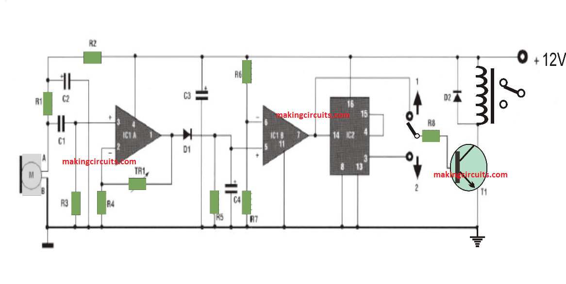
Using the selector DV in position 1, the relay is activated as soon as the capsule M receives a sound and turns off once the sound stops. However Having the selector switch DV in position 2, the relay switches ON when the MIC capsule gets a sound, and stays switched in that position even after the sound is removed.

And to de-energize the relay OFF you might requires another sound to hit the MIC and turn the relay OFF.

The microphone capsule is attached to the circuit with a little shielded cable, it can be positioned over a particular range (15 or 20 cm minimum) in this manner as to avoid the level of sensitivity of the microphone and prevent stary pick up from the vibrations of the relay.

The supply voltage has to be 12 Volts DC regulated. During idle conditions, the consumption is approximately 1 mA, with the relay activated it is around 45 mA.

To be able to perform the setting up for this sensitive clap switch circuit, the layout of the components has to be cautiously implemented.

Parts List

All resistors are
Of 1/4 watt unless stated otherwise

R1 = 6.8K
R2 = 4.7 K
R3 = 39 K
R4 = 5.6 K
R5 = 470 K
R6 = 470 K
R7 = 100 K
R8-3.9 K
TRl = 2.2M
CI = 100 nF.
C2 = 22uF16Velec.
C3 = 22uF16Velec.
C4 = luF16Velec.
D1-1N4148
D2 = 1N4148
Tl = 2N1711
IC1 = LM324
IC2-4017
DV = Selector.
M = Micro capsule.
RL1 = 12 V relay.
1 Support 14 pins.
1 Support 16 pins.

PCB design for this super sensitive clap switch circuit or voice operated relay circuit

clap switch PCB layout

You'll also like:

  • 1.  20 Best IC 741 based DIY Circuits
  • 2.  Simple Light Activated Switch Circuit
  • 3.  Sea Surf Sound Effect Simulator Circuit
  • 4.  Horse Pace Sound Simulator Circuit
  • 5.  How to Make an Opamp with Transistors (BJTs)
  • 6.  Keyboard Beep Circuit

About Admin

Hey friends, Thanks a bunch for stopping by this site! I am an engineer with a Bachelor of Engineering in Electronics and Telecommunication. One of my passions is gathering information from all sorts of electronics books and tutorials. I then take that information and compile it into a language that is super easy to understand. My goal is to make those complex electronics circuit concepts and technical terms much more accessible for all the new and budding electronics engineers out there. I can also design customized circuit diagrams as required by the users.
If you have any questions related to this field, please do not hesitate to drop a comment! I am always here and ready to help you out with any queries you might have. I cannot wait to hear from you!

Reader Interactions

Comments

  1. Ramakanth says

    December 25, 2018 at 12:36 pm

    I need this kit

    Reply
    • admin says

      January 1, 2019 at 8:52 pm

      I am sorry, we don’t make kits!

      Reply

Leave a Reply Cancel reply

Your email address will not be published. Required fields are marked *

Primary Sidebar

Categories

  • 3 Phase (4)
  • 8051 Microcontroller (1)
  • Arduino (11)
  • Audio and Amplifier (102)
  • Automation (8)
  • Battery Chargers (64)
  • Bicycle Projects (4)
  • Car and Motorcycle Projects (39)
  • Datasheets (10)
  • DIY Projects (5)
  • Electrical (15)
  • Free Energy (6)
  • Games Projects (2)
  • High Voltage (14)
  • Hobby Projects (30)
  • Household Circuits (2)
  • IC 555 Circuits (4)
  • Ignition Circuits (2)
  • Indicators (50)
  • Infrared (6)
  • Inverter Circuits (29)
  • Lights and Lamps (97)
  • Medical (8)
  • Meter and Tester Circuits (38)
  • Motor Driver (17)
  • New Circuits (56)
  • Oscillators (30)
  • Pets and Pests (5)
  • Power supply (81)
  • Protection Circuits (25)
  • PWM (8)
  • Remote Control (20)
  • Security and Alarm Circuit (48)
  • Sensors and Detectors (66)
  • Signal Processor (23)
  • Solar Controller Circuits (61)
  • SSR (3)
  • Temperature Controller (20)
  • Timer (25)
  • Transformerless (7)
  • Transmitters (12)
  • Tutorials (45)
  • UPS (2)
  • Voltage Regulators (57)
  • Water Sensor and Controller (29)
  • Home
  • Privacy Policy
  • Contact
  • Disclaimer
  • Copyright

© 2025 · Making Easy Circuits