While troubleshooting amplifier and audio related equipment, a signal injector circuit becomes one of the most essential tools, here we learn how to make a signal injector circuit.
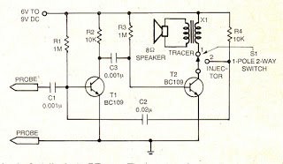
Here is a two in-one test instrument incorporating a signal injector and a signal tracer.
How it Works
If any audio equipment is not working, an audio signal can be injected at the volume control using this instrument.
If audio signal appears at the speaker of the set, you can be fairly sure that there is no trouble in the audio output stage.
Otherwise, the fault lies in the audio stage itself. Thus, by injecting the signal, the fault can be traced.
To check the RF stage, an audio signal can be injected in the RF stage.
If the output appears at the speaker, the equipment is working properly, other- wise the fault lies in the RF stage.
The Signal Injector Circuit besides injecting signals at RF, IF and AF stages can also detect signals at these frequencies.
1 X 1 is a 3V output transformer used in pocket transistor sets.

Chris says
Hello Again —–
No one has replied to my first ‘comment’ letter re: the SIGNAL
INJECTOR/TRACER project, so we’ll try one more time —
As I am interested only in the TRACER circuit — can the 1:1
transformer be exchanged for a load resistor/coupling capacitor
from the collector of T2 to the 8 ohm speaker ? I can’t find any
3v 1:1 miniature transformers on the internet, unless you know
where to look — only small, 600 ohm:600 ohm ones from China
on Ebay.
Please show a revised schematic if the above change can be
done.
Thank you kindly.
Chris
admin says
Hi, the transformer is actually an audio output transformer, which were used in old MW radios at the output stage. A 1:1 transformer will not be enough to amplify the signals to the speaker so it will not work.