• Skip to main content
  • Skip to primary sidebar

Making Easy Circuits

Learn and build electronic circuits

You are here: Home / Power supply / Simple 0-24V/5Amp Variable Power Supply Circuit with Transistors

Simple 0-24V/5Amp Variable Power Supply Circuit with Transistors

Last Updated on January 10, 2018 by Admin 7 Comments

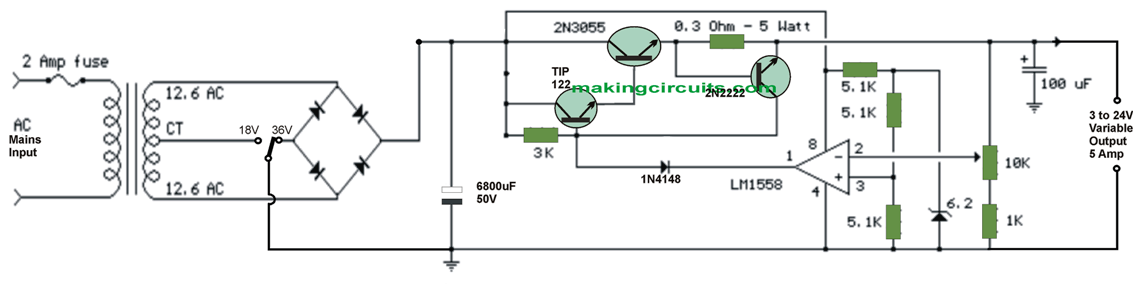
This 0-24V 5 Amp variable power supply circuit regulated mainly uses transistors for the power control and can be easily altered from 3 to 24 volts. In the shown design the current is restricted to 2 amps as displayed, although could be enhanced to 5 amps or even more by opting for a smaller sized current sensing resistor (0.3 ohm).

The 2N3055 and TIP122 transistors must be installed on appropriate heat sinks and the current sense resistor needs to be specified at 3 watts or maybe more.

Voltage regulation is actually managed through 1/2 of a 1558 or 1458 op-amp. The 1458 could be replaced in the circuit listed below, however it is advised the supply voltage to pin 8 always be restricted to 30 VDC, that may be attained with the addition of a 6.2 volt zener or 5.1 K resistor in series with pin 8.

The highest level DC supply voltage intended for the 1458 and 1558 is 36V and 44V correspondingly. The power transformer needs to be competent at the specified current yet sustaining an input voltage of a minimum of 4 volts greater than the specified output, however, not beyond the absolute maximum supply voltage of the op-amp using nominal load circumstances.

The power transformer displayed is actually a center tapped 25.2 volt AC / 2 amp device that may offer regulated outputs of 24 volts on 0.7 amps, 15 volts with 2 amps, or 6 volts at 3 amps.

The 0-24V, 5 amp variable power supply output will be acquired making use of the center tap of the transformer using the switch within the 18 volt situation. Just about all parts should really be gotten from any reputed online electronic store along with the opamp IC.


0-24V/5Amp Variable Power Supply Circuit with Transistors

You'll also like:

  • 1.  High Current LM317 Variable Power Supply Circuit
  • 2.  Transformerless Power Supply for LED String Lights
  • 3.  5V, 12V Buck Converter Circuit SMPS 220V
  • 4.  LM317 Adjustable Power Supply Circuit
  • 5.  Simplest Variable Power Supply Circuit
  • 6.  1A Voltage Regulator better than 7805, 7812

About Admin

Hey friends, Thanks a bunch for stopping by this site! I am an engineer with a Bachelor of Engineering in Electronics and Telecommunication. One of my passions is gathering information from all sorts of electronics books and tutorials. I then take that information and compile it into a language that is super easy to understand. My goal is to make those complex electronics circuit concepts and technical terms much more accessible for all the new and budding electronics engineers out there. I can also design customized circuit diagrams as required by the users.
If you have any questions related to this field, please do not hesitate to drop a comment! I am always here and ready to help you out with any queries you might have. I cannot wait to hear from you!

Reader Interactions

Comments

  1. Larry Guevara says

    June 24, 2022 at 4:17 am

    Parts list would be nice.

    Reply
  2. Jun Balista says

    February 12, 2021 at 7:18 am

    how do we control the current from say 0.3 amps to 5.0 A amps ? can you suggest a modification to make it possible?

    Reply
    • admin says

      February 20, 2021 at 9:08 pm

      connect a 1k pot outer leads across the 0.3 ohm resistor, and connect the 2N2222 base with the center wiper lead of the pot

      Reply
  3. Liezl Asilo says

    September 10, 2017 at 9:19 am

    what is current and voltage rating of your transformer?
    Can we use LM748 instead of LM1558? We can talk through email ([email protected]) Thank you 😀

    Reply
    • admin says

      September 11, 2017 at 9:45 pm

      voltage is given in the diagram, current can be upto 10 amps, you can use any good opamp as per your preference

      Reply
  4. Liezl Asilo says

    September 7, 2017 at 8:57 pm

    Hi! May I ask some questions about this circuit? Please send me an email. Thanks 🙂

    Reply
    • admin says

      September 8, 2017 at 8:56 pm

      please go ahead with your question….

      Reply

Leave a Reply Cancel reply

Your email address will not be published. Required fields are marked *

Primary Sidebar

Categories

  • 3 Phase (4)
  • 8051 Microcontroller (1)
  • Arduino (11)
  • Audio and Amplifier (102)
  • Automation (8)
  • Battery Chargers (64)
  • Bicycle Projects (4)
  • Car and Motorcycle Projects (39)
  • Datasheets (10)
  • DIY Projects (5)
  • Electrical (15)
  • Free Energy (6)
  • Games Projects (2)
  • High Voltage (14)
  • Hobby Projects (30)
  • Household Circuits (2)
  • IC 555 Circuits (4)
  • Ignition Circuits (2)
  • Indicators (50)
  • Infrared (6)
  • Inverter Circuits (29)
  • Lights and Lamps (97)
  • Medical (8)
  • Meter and Tester Circuits (38)
  • Motor Driver (17)
  • New Circuits (56)
  • Oscillators (30)
  • Pets and Pests (5)
  • Power supply (81)
  • Protection Circuits (25)
  • PWM (8)
  • Remote Control (20)
  • Security and Alarm Circuit (48)
  • Sensors and Detectors (66)
  • Signal Processor (23)
  • Solar Controller Circuits (61)
  • SSR (3)
  • Temperature Controller (20)
  • Timer (25)
  • Transformerless (7)
  • Transmitters (12)
  • Tutorials (45)
  • UPS (2)
  • Voltage Regulators (57)
  • Water Sensor and Controller (29)
  • Home
  • Privacy Policy
  • Contact
  • Disclaimer
  • Copyright

© 2025 · Making Easy Circuits