• Skip to main content
  • Skip to primary sidebar

Making Easy Circuits

Learn and build electronic circuits

You are here: Home / Lights and Lamps / 4 Watt LED Driver Circuit Using IC LM338

4 Watt LED Driver Circuit Using IC LM338

Last Updated on November 14, 2024 by Admin Leave a Comment

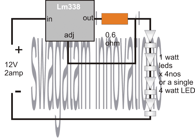
This five-watt LED driver uses the IC LM338 to safely light a four-watt LED in a constant current circuit mode.

As is well known, the integrated circuit LM338 is an extremely flexible device for managing voltages and current quantities.

Circuit Working

The LM338 configuration in the given concept is intended for an automatic current control.

In particular, white LEDs require a precisely measured input, and practically, the current flowing to them needs to be tightly regulated.

It ensures that the output's current is constantly tracked by the ADJ pin and is never permitted to exceed the preset level established by the 0.6 Ohm resistor through the connection of its ADJ pin to the output.

Because this LM338 can readily drive one to five one-watt LEDs, each with its own current-limiting resistor, it can sustain at least three amps of current.

It is possible to play around with different values for the current limiting resistors in order to increase the brightness levels of the LEDs. Despite this, anything lower than fifty Ohms is not worth attempting since it may permanently harm the LEDs.

Understanding the Circuit Design

A regulated DC power source that can provide 12 volts at three amps or higher might be used as the input for the LM 338 integrated circuit.

For best results, the IC LM 338 must be installed on a heatsink.

A 1N5408 rectifier diode is suitable for the intended use if the input diode has a 3 amp rating.

A 12 volt battery, such as one from a vehicle, may be used as the input if the circuit is meant to run outside.

The suggested 4 watt LED driver circuit is therefore particularly well suited for lighting up car interiors, such as with a roof light or other fixture.

Calculating the Limiting Resistor

Assuming only one 4 watt LED is connected, the resistor value may be chosen using the formula R = 1.25/LED current.

Here, LED current = 4/3.3 = 1.21A

Therefore R = 1.25/1.21 = about 1 ohm (0.6 is not correct)

R watts = 1.25 x 1.21 = 1.5 or 2 watt

for 4 nos 1 watt LEDs, total current is 300mA

Therefore R = 1.25/0.3 = 4 ohms

Circuit Diagram

4 watt led current controlled driver from 12V supply

Parts List

ComponentSpecification
LM338 ICVoltage Regulator IC (1 piece)
LEDs (1 watt, 350 mA)1 watt, 350 mA (4 pieces)
Resistor (0.6 Ω, 1 watt)0.6 Ω, 1 watt (1 piece)

You'll also like:

  • 1.  2 Simple 40 watt Fluorescent Tube Emergency Light Circuit
  • 2.  Simple 1 Watt LED Driver Circuit
  • 3.  Make this IC 741 Automatic Day/Night Street Light Circuit
  • 4.  Simplest Strobe Light Circuit
  • 5.  Driver Circuit for CREE XM-L T6 LED
  • 6.  8 LEDs Light up Sequentially, then Shut OFF and Repeat: Circuit Diagram

About Admin

Hey friends, Thanks a bunch for stopping by this site! I am an engineer with a Bachelor of Engineering in Electronics and Telecommunication. One of my passions is gathering information from all sorts of electronics books and tutorials. I then take that information and compile it into a language that is super easy to understand. My goal is to make those complex electronics circuit concepts and technical terms much more accessible for all the new and budding electronics engineers out there. I can also design customized circuit diagrams as required by the users.
If you have any questions related to this field, please do not hesitate to drop a comment! I am always here and ready to help you out with any queries you might have. I cannot wait to hear from you!

Reader Interactions

Leave a Reply Cancel reply

Your email address will not be published. Required fields are marked *

Primary Sidebar

Categories

  • 3 Phase (4)
  • 8051 Microcontroller (1)
  • Arduino (11)
  • Audio and Amplifier (102)
  • Automation (8)
  • Battery Chargers (64)
  • Bicycle Projects (4)
  • Car and Motorcycle Projects (39)
  • Datasheets (10)
  • DIY Projects (5)
  • Electrical (15)
  • Free Energy (6)
  • Games Projects (2)
  • High Voltage (14)
  • Hobby Projects (30)
  • Household Circuits (2)
  • IC 555 Circuits (5)
  • Ignition Circuits (2)
  • Indicators (50)
  • Infrared (6)
  • Inverter Circuits (29)
  • Lights and Lamps (97)
  • Medical (8)
  • Meter and Tester Circuits (38)
  • Motor Driver (17)
  • New Circuits (56)
  • Oscillators (30)
  • Pets and Pests (5)
  • Power supply (80)
  • Protection Circuits (25)
  • PWM (9)
  • Remote Control (20)
  • Security and Alarm Circuit (48)
  • Sensors and Detectors (66)
  • Signal Processor (23)
  • Solar Controller Circuits (62)
  • SSR (3)
  • Temperature Controller (20)
  • Timer (25)
  • Transformerless (7)
  • Transmitters (12)
  • Tutorials (45)
  • UPS (2)
  • Voltage Regulators (57)
  • Water Sensor and Controller (29)
  • Home
  • Privacy Policy
  • Contact
  • Disclaimer
  • Copyright

© 2025 · Making Easy Circuits