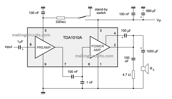
In this post we study a very simple yet powerful 12 watt amplifier circuit using a single chip TDA1020 and few other handful of passive components.
The TDA1020 is designed in the form of a monolithic integrated 12 W audio amplifier in a 9-lead single in-line (SIL) plastic package.
Typically the unit is principally created for a car radio amplifier. With a supply voltage of VP= 14.4 V, an output power of 7 W could be supplied right into a 4 Q load and 12 W into 2 Q.
In order to avoid interferences and car ignition impulses arriving through the supply rails into the IC, frequency restricting is employed outside of the music range within the preamplifier and the power amplifier.
The absolute maximum supply voltage of 18 V helps make the IC additionally ideal for mains operated radio receivers, audio recorders or record players.
On the other hand, when the supply voltage is higher over 18 V ( < 45 V), the IC TDA1020 won't be destroyed (since the IC is internally load-dump secured).
Additionally a short-circuiting of the output to ground (a.c.) is not going to kill the IC. Over Heat security is furthermore integrated.
For a exclusive attribute, the TDA1020 amplifier circuit features a very low stand-by current program.
The TDA1020 can be pin-to-pin compatible along with the TDA1010.
Pinout Specifications of the IC TDA1020
Pin#1: Negative supply (substrate)
Pin#2: Output power stage
Pin#3: Positive supply (VP)
Pin#4: Bootstrap
Pin#5: Ripple rejection filter
Pin#6: Input power stage
Pin#7: Output preamplifier
Pin#8: Input preamplifier
Pin#9: Negative supply
Leave a Reply