Here we will see how we can make a simple 20 amp 24V adjustable power supply circuit using an LM317 IC and afew 2N3055 transistors configured in their emitter follower mode.
This circuit is quite popular among vehicles or busses in which the batteries offer 24V including different things within the electrical circuit where 12V may be essential. Although a lot of installers make use of a cable through the association of the pair of batteries to obtain 12V which means a lot of wire, and this is not really advised because this impacts on the proper efficiency of the accumulators and also causes discharging of the battery more along with all the accompanying issues that this may result in.
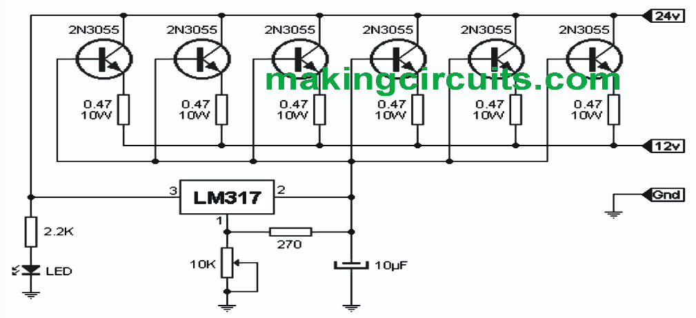
As evident, this 20 Amp adjustable power supply circuit is actually simply an adjustable integrated voltage regulator which can be seen engaged on several parallel power transistors. These transistors carry out the major function as may be witnessed while the regulator IC simply manages maintaining these correctly. Where it is shown as the 24v connector could be the input through the batteries. The indicated 12v connection may be the output and the Gnd connection needs to be grounded. Needless to say, all components (transistors and integrated) should be mounted on a large heatsink for facilitating good heat dissipation as well as must be electrically isolated from the heatsink metal.
Adjustment:
Position the 10K preset at the maximum go (or open the 10K preet connection) and hook up to the converter output lamp 12V / 50W. On the output access, link-up the batteries in series with what may be accomplished as 24V. At the output side, parallel to the lamp, attach a continuous scale tester having a appropriate rating (about 50V). Now begin to turn the preset so that the lamp lights and the tester shows 12V...that's all, your 20 amp 24V power supply circuit is set and ready to be used
bagaimana cara menghitung/ menentukan nilai resistor emitor 2N3055 & apa fungsinya.
Hi Admin;
I used also BD139 for the current control in the circuit but my circuit has only one pc of tip3055 at the output. My question is:
It is possible to connect parallel tip3055 and 2n3055 or both should be the same type? And other point is that the (+) voltage is being gained from emitter of the power transistor on the some circuits whereas here on the above circuit output is from the collector of the transistor? Please share your opinion about the situtation.
Hi Suat,
tip3055 and 2n3055 both can be used in parallel in the above circuit.
The 24V Dc is the input supply which is applied to the collectors of the 2N3055 transistors. The outputs are taken from the emitters of all the 2N3055 transistors.
Admin should have mentioned the actual typical low DC gain of the 2N3055 does require a relatively high base current of around 3/4 amp for full saturation, but as each transistor is expected to provide only something just over 3 amps, a base current of 0.15/0.2 amps should do the trick if the response is reasonably linear.
6 x 0.2 = 1.2 amps, which is uncomfortably close to the 1.5 amp rating of the LM317.
The circuit does assume the transistors are all matched for gain when in reality that is unlikely and when so many cheap “seconds” are on the market the actual gain can vary wildly causing, perhaps, a single transistor to do the lion’s share of the work.
The circuit has the benefit of a belt and braces approach to the problem – where each of the power transistors are relatively unstressed, however should one decide to short circuit, whatever 12 volt device is connected will receive the full force of the 24 volt supply so it would be good if the belt and braces theme was taken a stage further and provide some failsafe protection for the possibly expensive equipment that would connected to it…
The transistors have been already provided with individual emitter limiting resistors to ensure they don’t get into a thermal runaway situation. Moreover the transistors are supposed to be mounted over a common heatsink so that they share the heat uniformly reinforcing the safety further.
concerning the “Simple 24V 20 Amp Adjustable Power Supply Circuit”
what is the simple solution for:
each 2N3055 draws around 3 amps at its base at the desired voltage in order to produce something around 9 amps at the output for the desired voltage
6- 2N3055 in parrell would then draw 18amps at the desired voltage on the Base circuit feeding the 6 – 2N3055’s ??
a single LM317 can only produce 1.5 amps heavily heatsinked at the desired voltage output ?
how would it require 3 amps at base to produce 9 amps at emitter?? your calculation is incorrect.