• Skip to main content
  • Skip to primary sidebar

Making Easy Circuits

Learn and build electronic circuits

You are here: Home / Audio and Amplifier / Simple 300 Watt Power Amplifier Circuit using Transistors

Simple 300 Watt Power Amplifier Circuit using Transistors

Last Updated on June 6, 2025 by Admin 12 Comments

For hobbyists and music lovers who are interested to get more audio power from a simple amplifier circuit, here we present this 300 watt power amplifier circuit capable of delivering overloaded 300w RMS over a load of 8 ohms, and over 350 watts with 4 Ohm speakers.

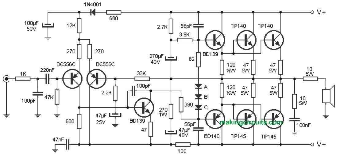
The proposed amplifier circuit uses complementary transistors to achieve the intended high power with Hi-Fi quality. The unit is powered with a 45V + 45V supply, with current not more than 7 amps. Most of the incorporated transistors barring the BC556C must be mounted on the heatsink, which must be prferably fixed over one of the sides of the cabinet to facilitate proper dissipation.

The diodes marked A, B and C are 1N4007 and these too must also be mounted on the heat sink but with thermal grease. The music fed to the amplifier input must be 1Vpp standard line.

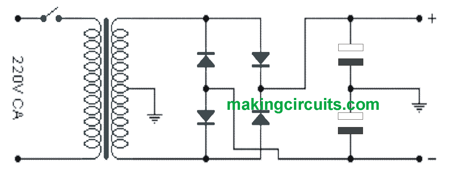
As shown in the diagram the specified power supply does not need to be a complex stabilized but must be adequately filtered using high value filter capacitors. I personally recommend the following specifications for this 300 watt amplifier circuit  power supply:

You can use a transformer with a secondary section that has a central socket 32-0-32 (or 64V with central socket). For a mono configuration it must have a current of 5A, for stereo 10A. The diodes should be at least 100V by 8A for mono and 100V for 16A  for stereo. The capacitors must be 4700μF 63V each. Do not use higher voltages as this would affect the working curve of the capacitor (not filtering optimally).

You'll also like:

  • 1.  Precision Guitar Tuner Circuit
  • 2.  Mouth Operated Music Synthesizer Circuit
  • 3.  Amplifier Circuits Using CMOS ICs
  • 4.  High Power Headphone Amplifier Circuit
  • 5.  Realistic Machine Gun Sound Effect Generator Circuit
  • 6.  Simple 100 Watt Amplifier Circuit using a Single IC

Tagged With: 300, Amplifier, Power, Simple, Transistors, watt

About Admin

Hey friends, Thanks a bunch for stopping by this site! I am an engineer with a Bachelor of Engineering in Electronics and Telecommunication. One of my passions is gathering information from all sorts of electronics books and tutorials. I then take that information and compile it into a language that is super easy to understand. My goal is to make those complex electronics circuit concepts and technical terms much more accessible for all the new and budding electronics engineers out there. I can also design customized circuit diagrams as required by the users.
If you have any questions related to this field, please do not hesitate to drop a comment! I am always here and ready to help you out with any queries you might have. I cannot wait to hear from you!

Subscribe
Login
Notify of


12 Comments
Newest
Oldest Most Voted
Inline Feedbacks
View all comments
Elis clementino
2 years ago

Muito bom esse amplificador, qualidade sonora boa.

0
Reply
Joe
2 years ago

Does this circuit have a volume control or can a volume/tone control be added later?

0
Reply
Author
Admin
2 years ago
Reply to  Joe

No, there’s no built-in volume or tone control in the shown design. You can add a separate tone-control/volume-control module at the input side of the amplifier

0
Reply
Alex De Groote
3 years ago

De emmiter weerstanden zijn 47 ohm , dat is toch biet juist ?

0
Reply
Author
Admin
3 years ago
Reply to  Alex De Groote

yes the emitter resistors are 47 ohms.

0
Reply
Esrael Mathewos Isre
4 years ago

why is the resistor series with speaker?

0
Reply
Author
Admin
4 years ago
Reply to  Esrael Mathewos Isre

To limit excessive current

0
Reply
Murtala Abdulhamid
4 years ago

please kindly send me the latest power amplifier circuit diagram thanks

0
Reply
Author
Admin
4 years ago
Reply to  Murtala Abdulhamid

the above amplifier is the latest one, and is an universal evergreen model…

0
Reply
Juan
3 years ago
Reply to  Murtala Abdulhamid

El amplificador no puede funcionar así con una resistencia en serie de 10 Ohms 5 W en serie con el parlante. Todos copian y pegan.

0
Reply
Author
Admin
3 years ago
Reply to  Juan

Then what should it be its value? Please update it.

0
Reply
Cesar
8 months ago
Reply to  Juan

just to discuss the 10 ohm resistor. Perhaps the schematic was copied incompletely. There is normally a (hand made) wire INDUCTOR in parallel with the 10 ohms. The work instructions read like: “take 20 inches of #14 wire, and wrap the wire around the 10 ohm resistor” and this becomes the OUTPUT NODE of the amplifier

0
Reply

Primary Sidebar

Categories

  • 3 Phase (4)
  • 8051 Microcontroller (1)
  • Arduino (11)
  • Audio and Amplifier (103)
  • Automation (8)
  • Battery Chargers (64)
  • Bicycle Projects (4)
  • Car and Motorcycle Projects (40)
  • Datasheets (10)
  • DIY Projects (6)
  • Electrical (15)
  • Free Energy (6)
  • Games Projects (2)
  • High Voltage (14)
  • Hobby Projects (30)
  • Household Circuits (2)
  • IC 555 Circuits (4)
  • Ignition Circuits (2)
  • Indicators (51)
  • Infrared (6)
  • Inverter Circuits (29)
  • Lights and Lamps (97)
  • Medical (8)
  • Meter and Tester Circuits (38)
  • Motor Driver (17)
  • New Circuits (56)
  • Oscillators (30)
  • Pets and Pests (5)
  • Power supply (84)
  • Protection Circuits (25)
  • PWM (8)
  • Remote Control (20)
  • Security and Alarm Circuit (48)
  • Sensors and Detectors (66)
  • Signal Processor (23)
  • Solar Controller Circuits (61)
  • SSR (3)
  • Temperature Controller (20)
  • Timer (25)
  • Transformerless (7)
  • Transmitters (12)
  • Tutorials (45)
  • UPS (2)
  • Voltage Regulators (57)
  • Water Sensor and Controller (29)
  • Home
  • Privacy Policy
  • Contact
  • Disclaimer
  • Copyright

© 2025 · Making Easy Circuits

wpDiscuz