The intended 40-watt electronic ballast or choke is made to provide the greatest illumination along with excellent efficiency output for any 40-watt fluorescent tube.
Specifications on the buffer choke winding and torroid are also included, as is the PCB architecture for the suggested electronic fluorescent ballast.
Warning: This circuit is not isolated from Mains AC, exercise extreme caution while testing it.
Introduction
It's possible that LED technology, despite its great potential, may never be able to create lights as good as those made with contemporary electronic fluorescent ballasts.
This article discusses the circuit of an electronic tube light that is more efficient than LED lights.
Electronic chokes were relatively new ten years ago, and because of their high price and history of failures, not everyone favored them.
However, as the years went on, the gadget had some significant upgrades, and the outcomes were positive as they began to become more dependable and durable.
The electronic ballasts of today are far more reliable and efficient than before.
What separates electrical ballast from electronic ballast
What exactly specific benefit does employing electronic fluorescent choke provide over traditional electrical choke, then?
Understanding the operation of common electrical ballasts is essential to correctly interpreting the variances.
All that electrical ballast is is a basic mains voltage, high current inductor wound with hundreds of turns of copper wire above a laminated iron core.
Fundamentally, as is common knowledge, a fluorescent tube needs a strong starting current surge in order to flicker and for an electron flow to link between the two ends filaments.
As soon as this conduction is coupled, less current is needed to maintain it, which reduces lighting.
Electrical chokes are only needed to "push" the starting current; when combustion finishes, they provide increased impedance to manage the current supply.
Why we need a Starter in Electrical Chokes?
A starter ensures that the first "kicks" are sent via interrupted contacts, allowing the high currents needed to be produced by using the stored energy in the copper winding.
The starter ceases to operate as soon as the tube ignites. Since the ballast is directed via the tube, AC is now flowing through it continuously. Because of its inherent qualities, the tube delivers high impedance, which controls the current and contributes to maintaining excellent illumination.
But electrical chokes could grow highly inefficient, losing a lot of their energy by heat dissipation as a result of variations in voltage and inadequate calculation.
If you take accurate measurements, you'll discover that a 40 watt electrical choke fixture can use up to 70 watts of power—nearly twice as much than is needed. Moreover, it is impossible to fully understand the early blinks associated.
Why Electronic Chokes have Higher Efficiency
In terms of efficiency, however, electronic ballasts tend to be the complete opposite. The particular one that I constructed provided a light level which appeared more intense compared to usual while consuming only 0.13 amps of current at 230 volts.
For the past three years, i have continued running this circuit without experiencing any issues at all (although I did need to change the tube occasionally because it started to produce reduced light and darkened at the ends).
The circuit's efficiency is demonstrated by the current measurement, which shows that it uses just about 30 watts of electricity while producing an output light that is equal to 50 watts.
How the Electronic Choke Circuit Works
The suggested electronic fluorescent choke has a very simple operating concept. In the beginning the AC signal is rectified and filtered by the use of a bridge and capacitor arrangement.
A basic two transistor cross-coupled oscillator stage is included in the details that follow. This stage receives the rectified DC, and it begins oscillating at the desired high frequency right away.
Usually square wave oscillations, they are suitably buffered by an inductor before being utilized to light the attached tube when they are ignited.
The schematic depicts a 110 V model, which may be readily changed to a 230 V variant by making minor adjustments.
The instructions for constructing a 40 watt DIY electronic fluorescent choke circuit yourself using common components are provided in the accompanying drawings.
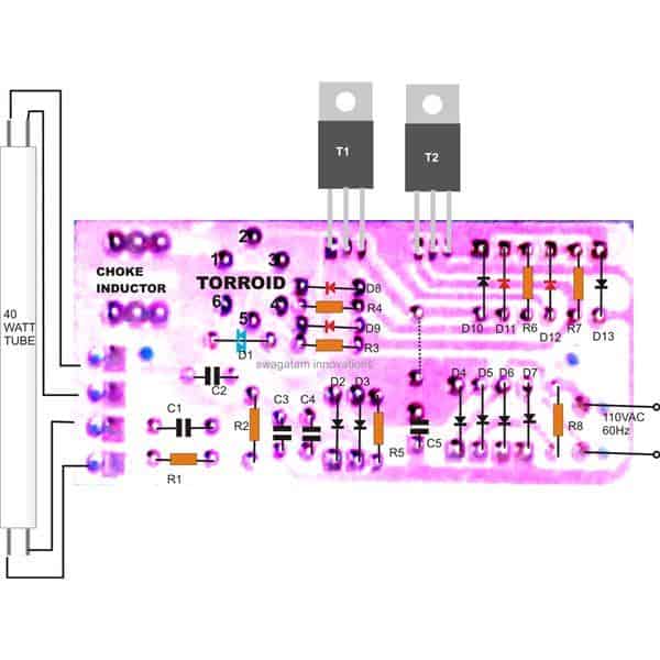
PCB Component Layout
WARNING: THE CIRCUIT MAY BECOME UNPREDICTABLE AND MAY BLOW-OFF AT ANY TIME IF A MOV AND A THERMISTER ARE NOT INCLUDED AT THE SUPPLY INPUT.
FOR EVEN BETTER EFFICACY AND LONGER LIFE, MOUNT THE TRANSISTORS OVER SEPARATE, 4*1 INCH HEATSINKS.
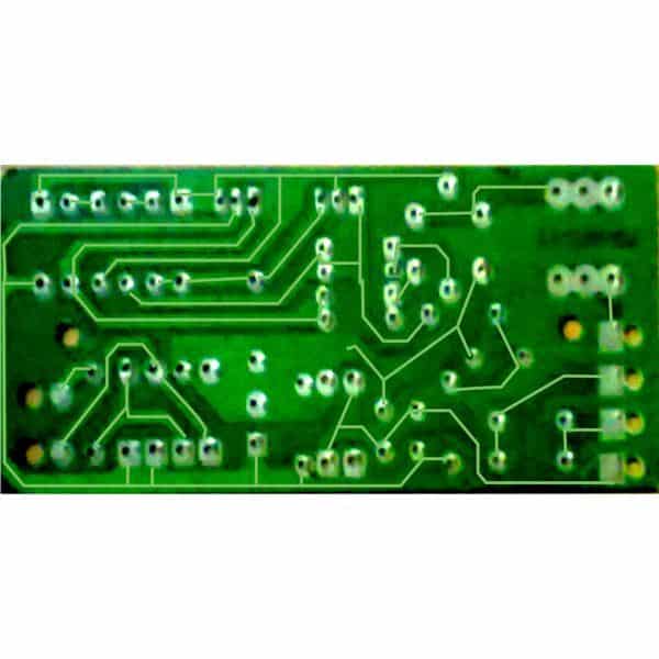
PCB Track Layout
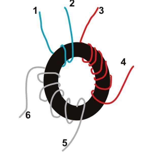
Torroid Inductor
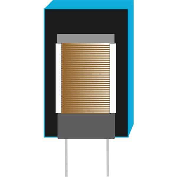
Choke Inductor
Parts List
| Component | Value | Tolerance | Power Rating | Type |
|---|---|---|---|---|
| R1 | 330 kΩ | 1% | - | MFR |
| R2 | 330 kΩ | 1% | - | MFR |
| R5 | 330 kΩ | 1% | - | MFR |
| R3 | 47 Ω | 5% | - | CFR |
| R4 | 47 Ω | 5% | - | CFR |
| R6 | 47 Ω | 5% | - | CFR |
| R7 | 47 Ω | 5% | - | CFR |
| R8 | 2.2 Ω | - | 2 watts | - |
| C1 | 0.0047 μF / 400V | - | - | PPC |
| C2 | 0.047 μF / 400V | - | - | PPC |
| C3 | 0.033 μF / 400V | - | - | PPC |
| C4 | 0.033 μF / 400V | - | - | PPC |
| C5 | 4.7 μF / 400V | - | - | Electrolytic |
| D1 | Diac DB3 | - | - | - |
| D2-D7 | 1N4007 | - | - | - |
| D8-D9 | 1N4148 | - | - | - |
| D10,D13 | B159 | - | - | - |
| D11-D12 | 1N4148 | - | - | - |
| T1,T2 | 13005 Motorola | - | - | - |
Heatsinks are required for T1 and T2.