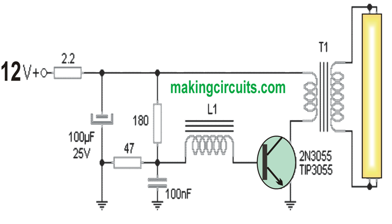
The first circuit of a 40 watt fluorescent emergency lamp is centered around the theory of oscillating on the primary of a transformer to accomplish a secondary high voltage able to ionizing the gas protected inside the tube and thus enable it to be illuminated
Inside the circuit each of the resistors are 1W and 12W rated. The transistor has to be effectively heatsinked.
How the Circuit Works
As demonstrated, it has an oscillator circuit which initially appears that it would not work. However just look a little bit in depth towards the configuration of L1 / T1 allows us to understand how the oscillator is turned ON
How to Wind the Inductor L1
Over a ferrite rod coil the two transformer winding (L1) are attached in the form of the inductor of transistor (T1). Therefore we have the oscillator circuit in the feedback mode. For every single cycle of a percentage of power transistor it is recognized by the winding L1 which retriggers the transistor and consistently runs the system. However , exactly how this inductor is created? Let's learn it
First we have to get a ferrite rod for example which are found in AM radios 6cm long.

Cover this bar with 60 turns of enameled wire 1 mm thick. This becomes the primary winding, which will be connected with the power transistor. Once this primary winding is completed fix it firmly in place by wrapping a layer of transparent insulation tape, and if possible secure the wire ends with fast curing epoxy glue or quick fix glue
After this wind the secondary winding on the center with 13 turns of 0.4mm enameled wire turns which will form the feedback winding or feedback loop L1. This winding will ensure that the initiates oscillating as soon as powered. As before secure this winding also with a layer of insulation tape and epoxy glue.
Finally now wind 450 turns of 0.4mm enameled wire forming the secondary side of T1. This winding is completed in three layers of 150 turns each, to create a decent layered winding and not a heaped bulk of wires. Make sure that between each layer a layer of insulation tape is wrapped to keep the layers intact and firmly wound. Done!...your inductor L1 for the 40 watt fluorescent emergency lamp circuit is complete
Setting up the Tube light Working
Before you turn this circuit ON, make sure the inductor is in the correct phase. This check this initially connect the fluorescent tube to the secondary and momentarily switch ON the system. If the tube does not light at all would indicate a incorrect phased primary side of (L1). Now simply swap the primary side wires with the transistor. Now check it again and this time you will find the tube illuminating brightly. But If the tube turns on at the first attempt (before reversing the wires, you need not do any mods!).
Next adjust the position of the coil L1 to the most optimal position over the ferrite and once done we could remove the limiting resistance (the 2.2 ohms) and allow the system to be powered directly.
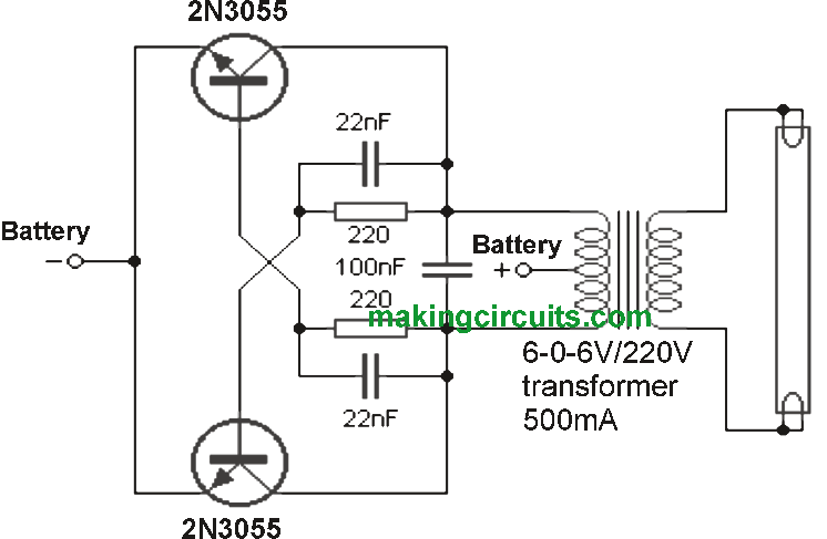
2) 40 watt 12 V Tube light Circuit using 2N3055
This simple 40 watt emergency tube light circuit permits one to hook up a fluorescent tube up to 40w in a vehicle or any other 12v source.
It is well suited for camping, motor homes and cabins intended for trucks or buses. Because of its minimal consumption it can be applied as a complimentary or backyard light and keep the night on.
As witnessed in the diagram, the 40 watt emergency tube light circuit creates alternating high voltage coming from direct current. To get this done, it switches the transistors ON/OFF alternately.
When one 2N3055 transistor is in operating the other becomes open and the other way round. The opening / closing period of each transistor depends upon each RC bridge shaped through the 220 ohm resistor and the 22nF capacitor. The 100nF capacitor filters the line of probable static produced by the oscillator.
The transformer is normal, coming from those found in power supplies; Simply in this project is employed upside down.
The center tap of the secondary is straight coupled to the positive of the power, while negative offers current to the emitters of each power transistors. These transistors has to be installed on large heat sinks to avoid these from being destroyed by the heat.
The 40 watt fluorescent tube light may be the typical type and does not have to be brand new, may even operate a tube with conventional ballast and starter not work simply because within this type of circuit the filaments are generally not used. It may be attached either a directly or a spherical. No starter or reactance ought to be employed in this circuit.
PCB and Heatsink:
Although it is recommended, the usage of a printed circuit board with this project is not really essential
It may be assembled right into a metal case where the transistors are mounted on each side of the case. Make sure to utilize separators and insulators in these transistors, to prevent short circuits.
If you want to make use of the tube in a portable device, you should secure the components a lot more, to be able to endure the movements and shocks that this automobile will cause.
Power Transistors:
The 2N3055 power transistor required for this 40 watt fluorescent tube emergency light circuit may not be special, could be substituted by any equivalent with the voltage and current specs they may have. It is important is the fact that the two are identical, to ensure that there are actually no instabilities within the functioning of the oscillator and therefore of the technique on the whole.
Would anybody please help me how to calculate the frequency of this circuit based on the RC bridge. Any calculus or link where I can read about this?
Thank you in advance.
Emil
Sir you have used 6-0-6/220 @ 500mA transformer so what will be the voltage rating of the BATTERY.
Whether it should be 12V or a 6V Battery.Pl. clarify the doubt at the earliest.
With regards
SATISH KUMAR
Battery should be also 6V, at minimum 10AH