• Skip to main content
  • Skip to primary sidebar

Making Easy Circuits

Learn and build electronic circuits

You are here: Home / Tutorials / Simple Transistor Latching Circuit Explained

Simple Transistor Latching Circuit Explained

Last Updated on November 17, 2024 by Admin Leave a Comment

In this article, we’ll explore how to build a basic transistor latch circuit using only two BJTs (Bipolar Junction Transistors) and some resistors.

Introduction

A transistor latch is a type of circuit which, once activated by a brief high signal, maintains a consistently high output. It remains in this ‘on’ state as long as it has power, even if the initial signal disappears.

Such a circuit is handy for maintaining or ‘latching’ the output status of a circuit following an input prompt, keeping it stable even when the input is no longer present.

The sustained output can then be utilized to control a device, whether it’s through a relay, SCR (Silicon Controlled Rectifier), Triac, or directly by the transistor thats part of the output.

How it works

This article explains how to build a basic latch circuit with transistors, which is a low-cost project that only needs a few transistors and some basic parts.

simple transistor latch circuit diagram
If you move the part called C1 to a new spot... right between the base and emitter of T1, it will do a better job at preventing the circuit from accidentally switching on or off. Plus, you can use a smaller C1, may be just 0.22 microfarads.

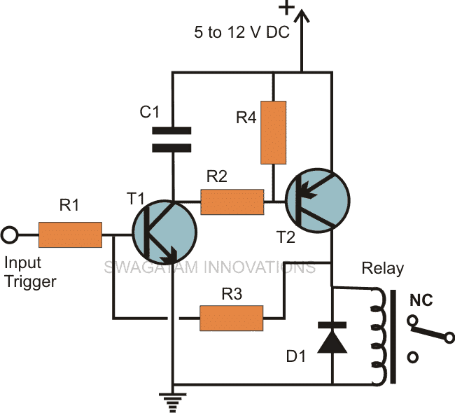
The diagram shows two transistors, T1 and T2, set up so that T2 copies what T1 does. If T1 gets a signal to start, T2 will also start, and if T1 stops, T2 will stop too.

T2 also helps to strengthen the signal making sure even tiny signals get noticed.

Heres what happens: When a little positive signal comes to T1, T1 quickly starts working and makes T2’s starting point go to zero.

Then T2 begins to work because of the negative push it gets from T1’s action.

It’s important to know that T1, an NPN type, works with positive signals, while T2, a PNP type, works with the negative energy created by T1.

Up to this point everything they do is pretty standard for transistors.

Feedback Resistor is the Crucial Latching Element

The resistor R3 in the circuit does something very clever. It takes a little bit of the power from one part of the circuit and sends it back to the start.

This loop keeps the circuit switched on, giving a steady positive power even if the original input signal that turned it on goes away.

Imagine if you had a relay (a type of switch) in this setup, once it’s turned on, it would stay on, even if you stopped pressing the button that started it.

Heres how it works, When T2 starts to act like T1, R3 takes some power from T2’s output and sends it back to T1. This makes T1 keep working non stop.

Theres also a part called C1 that makes sure the circuit doesn’t start by accident because of random signals or when you first turn it on.

To reset everything back to normal, you can either turn the whole circuit off and on again or use a push button to directly stop T1.

This kind of set-up is really useful, especially for things like security and alarm systems where you want something to stay on until you decide to turn it off.

Calculating Transistor Biasing

It can done with the following formulas

VBE = 0.7V

IE = (β + 1)IB ≅ IC

IC = βIB

Parts List

  • R1, R2, R4 = 10K,
  • R3 = 100K,
  • T1 = BC547,
  • T2 = BC557
  • C1 = 1uF/25V
  • D1 = 1N4007,
  • Relay = As preferred.
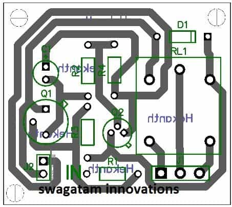
PCB Design

PCB design for transistor latch circuit

You'll also like:

  • 1.  Calculating LEDs in Series and Parallel (Easy Way)
  • 2.  Enhanced Stability in BJT Circuits with Voltage-Divider Bias Without Beta Factor
  • 3.  IC 555 Pinouts and Working Explained
  • 4.  Resistivity and Laws of Resistance
  • 5.  Relay Function Explained – How to Wire N/O and N/C Terminals
  • 6.  How to Calculate Timer Circuits using CMOS Gates

About Admin

Hey friends, Thanks a bunch for stopping by this site! I am an engineer with a Bachelor of Engineering in Electronics and Telecommunication. One of my passions is gathering information from all sorts of electronics books and tutorials. I then take that information and compile it into a language that is super easy to understand. My goal is to make those complex electronics circuit concepts and technical terms much more accessible for all the new and budding electronics engineers out there. I can also design customized circuit diagrams as required by the users.
If you have any questions related to this field, please do not hesitate to drop a comment! I am always here and ready to help you out with any queries you might have. I cannot wait to hear from you!

Reader Interactions

Leave a Reply Cancel reply

Your email address will not be published. Required fields are marked *

Primary Sidebar

Categories

  • 3 Phase (4)
  • 8051 Microcontroller (1)
  • Arduino (11)
  • Audio and Amplifier (102)
  • Automation (8)
  • Battery Chargers (64)
  • Bicycle Projects (4)
  • Car and Motorcycle Projects (39)
  • Datasheets (10)
  • DIY Projects (5)
  • Electrical (15)
  • Free Energy (6)
  • Games Projects (2)
  • High Voltage (14)
  • Hobby Projects (30)
  • Household Circuits (2)
  • IC 555 Circuits (5)
  • Ignition Circuits (2)
  • Indicators (50)
  • Infrared (6)
  • Inverter Circuits (29)
  • Lights and Lamps (97)
  • Medical (8)
  • Meter and Tester Circuits (38)
  • Motor Driver (17)
  • New Circuits (56)
  • Oscillators (30)
  • Pets and Pests (5)
  • Power supply (80)
  • Protection Circuits (25)
  • PWM (9)
  • Remote Control (20)
  • Security and Alarm Circuit (48)
  • Sensors and Detectors (66)
  • Signal Processor (23)
  • Solar Controller Circuits (62)
  • SSR (3)
  • Temperature Controller (20)
  • Timer (25)
  • Transformerless (7)
  • Transmitters (12)
  • Tutorials (45)
  • UPS (2)
  • Voltage Regulators (57)
  • Water Sensor and Controller (29)
  • Home
  • Privacy Policy
  • Contact
  • Disclaimer
  • Copyright

© 2025 · Making Easy Circuits