• Skip to main content
  • Skip to primary sidebar

Making Easy Circuits

Learn and build electronic circuits

You are here: Home / Meter and Tester Circuits / Simple Capacitor Tester Circuit

Simple Capacitor Tester Circuit

Last Updated on July 3, 2020 by Admin 1 Comment

This simple capacitor tester can be used to identify the values of unknown capacitors.

This bridge design was actually built to come across values for odd, unmarked or unknown capacitors.

Whilst not really being of good reliability, it can provide a great sign towards the value of the capacitor.

A well-known value component is positioned around terminals A-A, polarity is simply not essential, yet polarised capacitors should not be employed, and also should not be tested.

Fig1 10

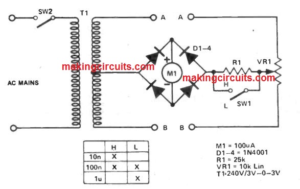
The capacitor under test is placed in B-B, the unit is turned on and VR1 moved till a optimum value reading is acquired on meter M1.

At this moment, a reading is extracted from the calibration scale within the pot which will at first should be calibrated in ratios, for example: 1000:1, 100:1, 10:1, 1:1, 1:10, 1:100 etc.

The unidentified value is now calculated using this reading. Original calibration is from known values.

To improve the range of this capacitor tester circuit switch SW1 continues to be incorporated to bypass R1.

Considering that the frequency utilized is 60 Hz through the AC line, ranges are minimal;

If an additional source have been employed, driving an audio output transformer, the usefulness of the unit might then be further more enhanced.

You'll also like:

  • 1.  How to Measure Thunderstorm Distance using an Electronic Circuit
  • 2.  Temperature Meter Circuit using RTD
  • 3.  Simple LED Voltmeter Circuit
  • 4.  Zener Diode Tester Circuit
  • 5.  How to Make a Digital Voltmeter, Ammeter Module Circuits
  • 6.  Small LED Weighing Scale Meter Circuit

Tagged With: Capacitor, Simple, Tester

About Admin

Hey friends, Thanks a bunch for stopping by this site! I am an engineer with a Bachelor of Engineering in Electronics and Telecommunication. One of my passions is gathering information from all sorts of electronics books and tutorials. I then take that information and compile it into a language that is super easy to understand. My goal is to make those complex electronics circuit concepts and technical terms much more accessible for all the new and budding electronics engineers out there. I can also design customized circuit diagrams as required by the users.
If you have any questions related to this field, please do not hesitate to drop a comment! I am always here and ready to help you out with any queries you might have. I cannot wait to hear from you!

Reader Interactions

Comments

  1. olufemi isiaka says

    March 17, 2021 at 8:34 am

    Building of 1kva pure sine wave inverters and transformer 1kva inverters

    Reply

Leave a Reply Cancel reply

Your email address will not be published. Required fields are marked *

Primary Sidebar

Categories

  • 3 Phase (4)
  • 8051 Microcontroller (1)
  • Arduino (11)
  • Audio and Amplifier (102)
  • Automation (8)
  • Battery Chargers (64)
  • Bicycle Projects (4)
  • Car and Motorcycle Projects (40)
  • Datasheets (10)
  • DIY Projects (5)
  • Electrical (15)
  • Free Energy (6)
  • Games Projects (2)
  • High Voltage (14)
  • Hobby Projects (30)
  • Household Circuits (2)
  • IC 555 Circuits (4)
  • Ignition Circuits (2)
  • Indicators (51)
  • Infrared (6)
  • Inverter Circuits (29)
  • Lights and Lamps (97)
  • Medical (8)
  • Meter and Tester Circuits (38)
  • Motor Driver (17)
  • New Circuits (56)
  • Oscillators (30)
  • Pets and Pests (5)
  • Power supply (83)
  • Protection Circuits (25)
  • PWM (8)
  • Remote Control (20)
  • Security and Alarm Circuit (48)
  • Sensors and Detectors (66)
  • Signal Processor (23)
  • Solar Controller Circuits (61)
  • SSR (3)
  • Temperature Controller (20)
  • Timer (25)
  • Transformerless (7)
  • Transmitters (12)
  • Tutorials (45)
  • UPS (2)
  • Voltage Regulators (57)
  • Water Sensor and Controller (29)
  • Home
  • Privacy Policy
  • Contact
  • Disclaimer
  • Copyright

© 2025 · Making Easy Circuits