• Skip to main content
  • Skip to primary sidebar

Making Easy Circuits

Learn and build electronic circuits

You are here: Home / Hobby Projects / Simple Clap Switch Circuit using Transistors (Tested)

Simple Clap Switch Circuit using Transistors (Tested)

Last Updated on January 10, 2018 by Admin Leave a Comment

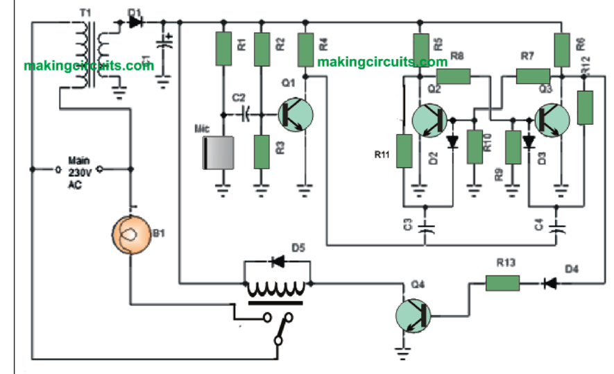
Below is a simple clap switch circuit for electronics amateurs which could turn on & off a bulb, Fan, Radio and so on., through the noise of clap. The sound of clap will be captured by a tiny mic which is indicated through a biasing resistor R1 within the circuit. The mic transforms sound influx into electrical pulses, that is additionally amplified by Q1. Transistor Q1 is employed as common emitter circuit to boost poor signals caught by the mic. Amplified result through the collector of transistor Q1 is fed back to the Bistable Multivibrator circuit generally known as flip-flop circuit.

simple clap switch circuit

How Clap Switch Works

Flip flop circuit is built through the use of a couple of Transistor, within our circuit Q2&Q3. Inside a flip-flop circuit, at any given time just one transistor triggers while the other remains cutoff and once it receives a trigger pulse coming from external source subsequently 1st transistor gets switched off and 2nd transistor is activated, therefore output of transistor will either be logic-0 or logic-1 plus it continues to be in a single status 0 or 1 until receives trigger pulse from a clap sound.
The pulse wave from a clap, which is converted as a trigger for the bistable flip-flop tends to make variations towards the output status which is contributory (opposite). End result of flip-flop, which can be in the reduced current state may not be able to push a relay so we employ a current amplifier circuit through the use of Q4 this is a common emitter circuit. The trigger from Q4 is linked to a Relay (Electromagnetic switch) that operates similar to a mechanical switch so it gets to be feasible for hooking up various other electrical equipment.
The relay contact is actually coupled to the mains power line and therefore it switches on/off just about any electrical appliance attached right through this relay.

Simple Clap Switch Part List:-
Resistors
R1=15 KΩ, R5,R6=1.5 KΩ
R2, R11, R12 = 2.2 MΩ, R13=2.2 KΩ
R3 = 270 KΩ, R4=3.3 KΩ
R7, R8 = 10 KΩ, R9, R10 = 27 KΩ
Capacitors
C1 = 1000 µf/16v
C2 = .01µf, C3, C4 = .047µf
Semi Conductors
Q1, Q2, Q3 = BC548
D2, D3, D4 = IN4148
D1, D5 = IN4007, Q4 = BC368
Sundries
T1 = 12v/500mA Transformer
Mic = Condenser Microphone
K1 = 12V Relay, B1= Bulb or Load

You'll also like:

  • 1.  How to Build a DIY Contact MIC Circuit
  • 2.  20 Best IC 741 based DIY Circuits
  • 3.  Simple Light Activated Switch Circuit
  • 4.  12 Simple NAND Gate Hobby Circuits – Schmitt Trigger Circuits
  • 5.  Automatic Signalling Circuit for Model Trains
  • 6.  Very Sensitive Clap Switch Circuit

About Admin

Hey friends, Thanks a bunch for stopping by this site! I am an engineer with a Bachelor of Engineering in Electronics and Telecommunication. One of my passions is gathering information from all sorts of electronics books and tutorials. I then take that information and compile it into a language that is super easy to understand. My goal is to make those complex electronics circuit concepts and technical terms much more accessible for all the new and budding electronics engineers out there. I can also design customized circuit diagrams as required by the users.
If you have any questions related to this field, please do not hesitate to drop a comment! I am always here and ready to help you out with any queries you might have. I cannot wait to hear from you!

Reader Interactions

Leave a Reply Cancel reply

Your email address will not be published. Required fields are marked *

Primary Sidebar

Categories

  • 3 Phase (4)
  • 8051 Microcontroller (1)
  • Arduino (11)
  • Audio and Amplifier (102)
  • Automation (8)
  • Battery Chargers (64)
  • Bicycle Projects (4)
  • Car and Motorcycle Projects (39)
  • Datasheets (10)
  • DIY Projects (5)
  • Electrical (15)
  • Free Energy (6)
  • Games Projects (2)
  • High Voltage (14)
  • Hobby Projects (30)
  • Household Circuits (2)
  • IC 555 Circuits (5)
  • Ignition Circuits (2)
  • Indicators (50)
  • Infrared (6)
  • Inverter Circuits (29)
  • Lights and Lamps (97)
  • Medical (8)
  • Meter and Tester Circuits (38)
  • Motor Driver (17)
  • New Circuits (56)
  • Oscillators (30)
  • Pets and Pests (5)
  • Power supply (80)
  • Protection Circuits (25)
  • PWM (9)
  • Remote Control (20)
  • Security and Alarm Circuit (48)
  • Sensors and Detectors (66)
  • Signal Processor (23)
  • Solar Controller Circuits (62)
  • SSR (3)
  • Temperature Controller (20)
  • Timer (25)
  • Transformerless (7)
  • Transmitters (12)
  • Tutorials (45)
  • UPS (2)
  • Voltage Regulators (57)
  • Water Sensor and Controller (29)
  • Home
  • Privacy Policy
  • Contact
  • Disclaimer
  • Copyright

© 2025 · Making Easy Circuits