Making a circuit to control a DC motor speed may look easy, but having a circuit which can provide enough torque to the motor even at lower speeds may not be so simple. In this post we discus how to build a simple DC motor speed controller circuit which can provide sufficient power or torque to the motor even at slower speeds.
Here's the question asked by one of the readers:
I've been working with little motors and am wondering if you have a simple circuit for controlling the speed of a motor. I experimented varying the voltage with a potentiometer, however the outcomes were poor because I had absolutely little control at lower motor speeds. Could you please explain why it didn't work and teach me how to fix it?
As folks started fiddling with robotics, small hobby motors made a significant reappearance. These small motors are quite useful for testing out different speed control based motor control concepts before investing in more expensive motors.
Nevertheless, because the motors have a lot of hysteresis, rheostat-style speed controls aren't particularly effective. Motors can be divided into two categories.
Voltage Control vs Frequency Control
The more common (and less expensive) types are operated by voltage, whereas others are likely to be controlled by frequency.
Typically DC motor speed control circuits alter the voltage, however this is a bad idea since it forces the motor to hang up at modest rpm.
Whenever you tried to use a basic rheostat-type controller, you ran across this issue. To initiate the motor, you have to increase the voltage sufficiently enough to combat the motor's hysteresis and any unresponsiveness caused by friction - remember, inexpensive motors have always been, by necessity, crudely manufactured.
PWM Control
Another form of motor speed control is the PWM control, which is by far the most efficient method of controlling DC motor speeds.
Here, the duty cycle, instead of the voltage, is varied in the motor, as shown in Figure 1 below.
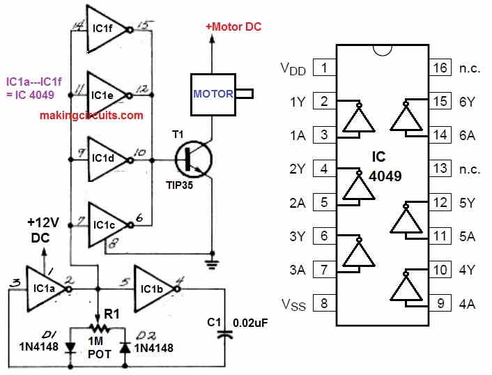
Even if the frequency remains unchanged, the two diodes will offer independent control of the positive (D1) and negative (D2) half of the capacitor's charging cycle.
The frequency may be estimated using the following formula:
f= 1/1.4RC
where f denotes frequency, and R is the potentiometer's total resistance. Since a single CMOS inverter doesn't really have much output power, the extra four inverters in the chip are paralleled to improve the circuit's driving power.
Use a 4049 inverter is recommended instead of any other CMOS inverter since it may output significantly more power.
Using IC 555 Frequency Control
Because it's only a rudimentary oscillator created from a 555 IC, the circuit in Fig. 2 below must be obvious.
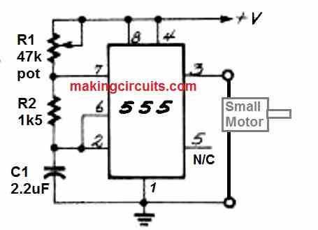
It's one of the simplest circuits to construct, and it's ideal for regulating smaller motors.
The incredible amount of driving capabilities built into the IC 555 chip tends to make this circuit appropriate for your basic motor control needs. Because the 555 can sink or source hundreds of milliamperes, it is simply capable of supplying current to all small motors.
You may change the output frequency between 10 Hz to 100 Hz using the values indicated in Fig. 2. All you must do is to experiment with the part values or put numbers into this equation:
f = 1.44/(R1+ 2R2)C
After this you can connect the necessary components to complete DC motor speed controller circuit using frequency adjustment.
It's worth noting that when the frequency rises, the duty cycle will rise as well. When adjusting motor speed, this is beneficial since low-speed response is more smoother when the clock has a longer on time.
IC 555 PWM Motor Controller with Reverse Forward Switch
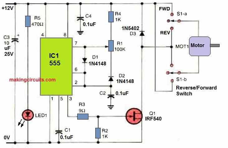
The next circuit above uses a single IC 555 for executing a PWM speed control over the connected DC motor. The pot R1 basically controls how fast or how slow the capacitor C2 can be charged or discharged.
This translates into a varying PWM output at the gate of the MOSFET. The MOSFET generates an equivalent amount of switching ON time or OFF time on the motor for controlling its speed.
The average ON time and OFF time or the duty cycle of the IC 555 output allows the motor speed to be controlled or varied accordingly.
The circuit also has a reverse/forward control switch which can be used to flip the motor rotation direction to move in the clockwise or anticlockwise direction, depending on the position of the switch.
Leave a Reply