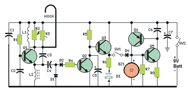
This circuit produces a beep and/or lights up a LED if a person hits the door-handle from outside. The alarm system will signal until the circuit might be switched-off. The over-all circuit is encapsulated in a compact plastic-type or timber container and needs to be hanged-up to the door-handle using a thick cable link up overhanging from the apex of the container. A wide-range level of responsiveness regulation permits the application the Door Alarm over a wide selection of doorway categories, grips and locking system. The gadget acquired confirmed dependable regardless if portion of the locking mechanism comes in contact with the wall structure (bricks, rocks, strengthened concrete), however may not adapt to all-metal entrance doors.The LED is extremely effective at setup.Circuit operation:Q1 shapes a free-running oscillator: its production bursts drive Q2 into saturation, therefore Q3 along with the LED are off. While portion of a body of a human comes in connection with a metallic hold electrically attached to the cord hook, the human body capacitance damps Q1 oscillations, Q2 biasing collapses off and the transistor evolves into non conducting. Consequently, current is able to stream into Q3 base and D3 lights up. In the event that SW1 is shut, a self-latching circuit created by Q4 & Q5 is activated and the beeper BZ1 is initialized. Once the body of a human portion sets off the handle, the LED switches-off but nevertheless the beeper goes on to buzz, on account of the self-latching actions of Q4 & Q5. To discontinue the beeper activity, the whole circuit needs to be switched-off breaking SW2. R3 is the level of sensitivity shaft, making it possible for to manage numerous entrance categories, handles and locking system. Notes:
L1 is put together winding 20 to 30 winding of 0.4mm. diameter enameled copper wire on R2 component iself and soldering the coil terminals to the resistor pins. You ought to pack R2 part thoroughly with coil winding: the concluding turn's wires may differ a little, subject to various 1 or 2W resistor styles specific measurement (meaning proportions when dealing with these components are 13-18mm. size and 5-6mm. diameter).
The hook up is fashioned from non-insulated cable 1 - 2mm. diameter (brass is a good choice). Its size can differ from about 5 to 10cm. (not very important).
In case the gadget is transfered regularly to various entrance doors, Trimmer R3 could be exchanged by a regular linear potentiometer installed with external knob for hassle-free installation.
To setup the gadget hang-up the hook up to the door-handle (with the doorway shut), unlock SW1 and switch-on the circuit. Fine-tune R3 until the LED just lights up, subsequently reverse little by little with the screwdriver (or the knob) until the LED is absolutely off. Right now, coming into contact with the door-handle with your palm the LED preferably should elucidate, and extinguishing off as soon as the palm is withdrawn. As a final point, press SW1 and the beeper is going to signal loudly while the door-handle might possibly be handled yet again, but nonetheless is not going to inhibit until SW2 is toggled off.
In common implement, remember to hang-up and power-on the gadget with SW1 opened up: as soon as pretty much all is properly worked out, SW1 could very well be toggled ON. This preventive step is recommended to steer clear of undesirable activating of the beeper.
Parts List

Leave a Reply