• Skip to main content
  • Skip to primary sidebar

Making Easy Circuits

Learn and build electronic circuits

You are here: Home / Audio and Amplifier / Simple Electronic Bagpipe Music Generator Circuit

Simple Electronic Bagpipe Music Generator Circuit

Last Updated on January 11, 2021 by Admin Leave a Comment

The electronic bagpipe circuit explained below will generate an exact replication of music that we generally hear from an original mouth operated bagpipe instrument.

Circuit Description

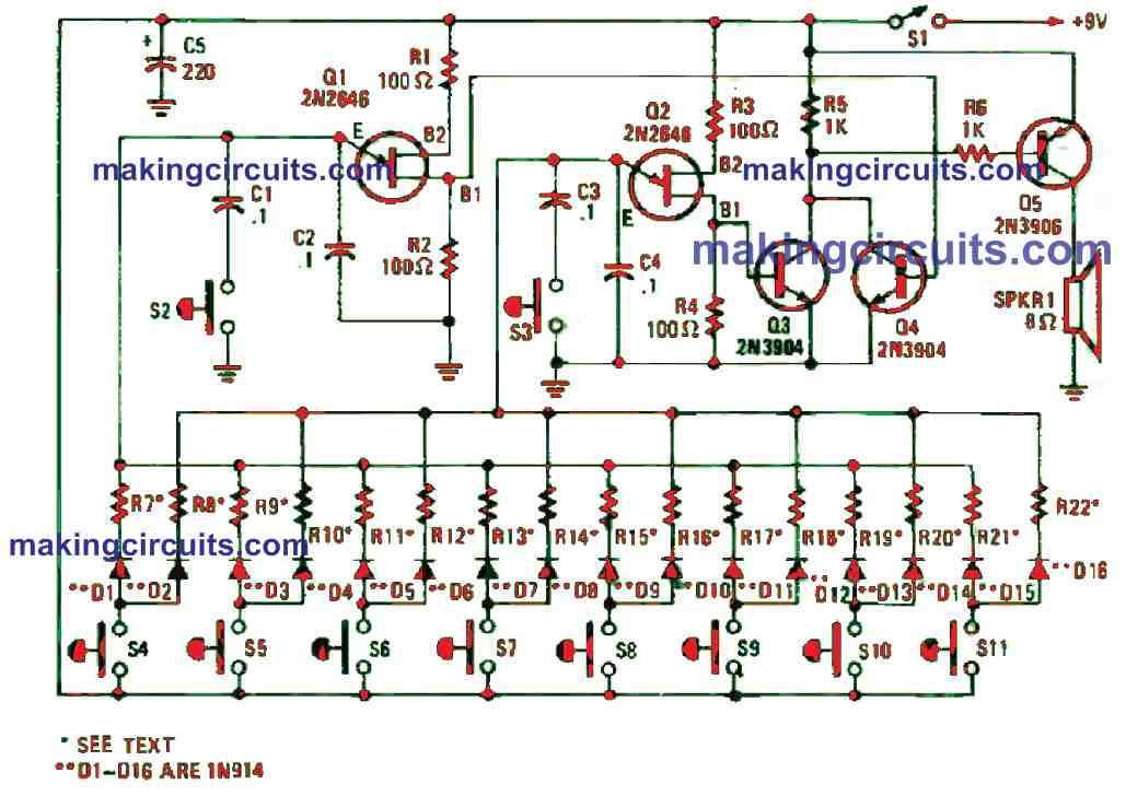
In the figure below, an easy-to-construct electronic bagpipe is shown. It is not only simple to built but also makes a perfect gift for children.
electronic bagpipe compressed

The circuit replicates the dual-tone drone sound that is generated by the unique wind instrument.

The working of the electronic bagpipe circuit is straightforward. Unijunction transistors Q1 and Q2 are attached in a similar audio-oscillator circuits. Every oscillator frequency is set by one of the two resistors selected by one of the pushbutton switches, S4 to S11.

The odd-numbered resistors namely R7 to R21, decide the frequency for the Q1 oscillator circuit whereas the even-numbered resistors R8 to R22 set the frequency for circuit of Q2.

Once S4 is pressed, the positive supply will be channelled to both R7 and R8 via isolation diodes D1 and D2. This causes the pair of oscillators to function. A thin, fast-rising positive pulse is generated at B1 of both Q1 and Q2 for every cycle of operation.

Transistors Q3 and Q4 work as a standard audio mixer whereby it is used to assimilate the pulses from each oscillator.

The mixed signal at the collectors of Q3 and Q4 is attached via R6 to the base of Q5. At this point, the signal gets amplified and powers an 8 Ω speaker, SPKR1.

The resistor values (R7 to R22) that work to decide the oscillator’s operating frequency must be chosen in pairs to produce the dual-tone drone of the bagpipe. Moreover, the values must be in the range of 3.3 k and 33 k.

Either by hearing or using a frequency counter, you can select the resistors and tune the instrument. The 16 resistors, R7 to R22 can be swapped with the exact amount of miniature trimmer potentiometers to simplify the tuning process.

Switches S2 and S3 are utilised to lessen the oscillator’s frequency by about one-half when closed to generate a new set of tones.

Construction of this electronic bagpipe circuit is simple, and you can build it on a perfboard or PCB and enclose it within a plastic or wooden case.

For better aesthetic, you can build a special enclosure that makes this circuit to look more professional.

Pats List

parts list bagpipe compressed

You'll also like:

  • 1.  Simple 20 watt Amplifier Circuit
  • 2.  24 Best Opamp Amplifier Circuits
  • 3.  Digital Volume Controller Circuit
  • 4.  Simple Telephone Amplifier Circuit
  • 5.  Door Buzzer Circuit
  • 6.  How to Build a DIY Contact MIC Circuit

About Admin

Hey friends, Thanks a bunch for stopping by this site! I am an engineer with a Bachelor of Engineering in Electronics and Telecommunication. One of my passions is gathering information from all sorts of electronics books and tutorials. I then take that information and compile it into a language that is super easy to understand. My goal is to make those complex electronics circuit concepts and technical terms much more accessible for all the new and budding electronics engineers out there. I can also design customized circuit diagrams as required by the users.
If you have any questions related to this field, please do not hesitate to drop a comment! I am always here and ready to help you out with any queries you might have. I cannot wait to hear from you!

Reader Interactions

Leave a Reply Cancel reply

Your email address will not be published. Required fields are marked *

Primary Sidebar

Categories

  • 3 Phase (4)
  • 8051 Microcontroller (1)
  • Arduino (11)
  • Audio and Amplifier (102)
  • Automation (8)
  • Battery Chargers (64)
  • Bicycle Projects (4)
  • Car and Motorcycle Projects (39)
  • Datasheets (10)
  • DIY Projects (5)
  • Electrical (15)
  • Free Energy (6)
  • Games Projects (2)
  • High Voltage (14)
  • Hobby Projects (30)
  • Household Circuits (2)
  • IC 555 Circuits (5)
  • Ignition Circuits (2)
  • Indicators (50)
  • Infrared (6)
  • Inverter Circuits (29)
  • Lights and Lamps (97)
  • Medical (8)
  • Meter and Tester Circuits (38)
  • Motor Driver (17)
  • New Circuits (56)
  • Oscillators (30)
  • Pets and Pests (5)
  • Power supply (80)
  • Protection Circuits (25)
  • PWM (9)
  • Remote Control (20)
  • Security and Alarm Circuit (48)
  • Sensors and Detectors (66)
  • Signal Processor (23)
  • Solar Controller Circuits (62)
  • SSR (3)
  • Temperature Controller (20)
  • Timer (25)
  • Transformerless (7)
  • Transmitters (12)
  • Tutorials (45)
  • UPS (2)
  • Voltage Regulators (57)
  • Water Sensor and Controller (29)
  • Home
  • Privacy Policy
  • Contact
  • Disclaimer
  • Copyright

© 2025 · Making Easy Circuits