• Skip to main content
  • Skip to primary sidebar

Making Easy Circuits

Learn and build electronic circuits

You are here: Home / Security and Alarm Circuit / Simple Fire Alarm Circuit

Simple Fire Alarm Circuit

Last Updated on November 17, 2024 by Admin 2 Comments

The post discusses a simple fire alarm circuit that you can build and install at home or shop for detecting a fire hazards and sounding an alarm.

At the point when there is a fire breakout in the room the temperature increments.

This ultra smaller and minimal effort blaze alert faculties fire breakout in light of this.

How the Circuit Works

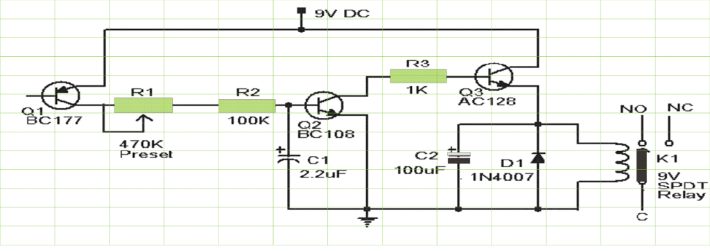
Transistor BC177 (Q1) is utilized as the fire blaze sensor here. At the point when the temperature expands the leakage voltage of this transistor likewise increments.

The circuit is planned so that when there is an increment in the above leakage of Q1, transistor Q2 will get one-sided.

Therefore when there is a flame breakout the transistor Q2 will be on. The emitter of Q2 (BC 108) is associated with the base of Q3(AC 128).

So when Q2 is ON Q3 will be likewise ON. The transistor Q3 drives the hand-off which is utilized to drive the load ie,light, bell, horn and so forth as an evidence of the fire.

The diode D1 is utilized as a free wheeling diode to shield it from back EMF created when hand-off is exchanged.

simple fire alarm circuit

Notes for the above Simple Fire Alarm Circuit

The Preset R1 can be utilized to any wanted temperature level for setting the alert ON.

This is not a lock type alarm, that is; when the temperature in the region of the sensor diminishes beneath the set point the caution stops.

The fire alarm circuit can be fueled utilizing  a 9V battery or a 9V battery eliminator.

All capacitors are electrolytic and must be evaluated no less than 10V.

The load can be associated through the C,NC,NO purposes of the relay contacts as per your need.

The adjustment could be possible utilizing a solder iron, and a thermometer.

Switch ON the power supply. Keep the tip of patching iron close to the Q1. Same time additionally keep the thermometer near to it.

At the point when the temperature achieves your coveted quality seal R1.

You'll also like:

  • 1.  Two Tone Alarm Circuit using Op-Amps
  • 2.  Bicycle Light and Alarm Circuit
  • 3.  How to Make a Power Interruption Alarm Circuit
  • 4.  Anti-Burglar Home Lighting Circuit
  • 5.  Basic Circuit for Making a Car Burglar Alarm
  • 6.  Screaming Alarm Circuit using IC 555

Tagged With: Alarm

About Admin

Hey friends, Thanks a bunch for stopping by this site! I am an engineer with a Bachelor of Engineering in Electronics and Telecommunication. One of my passions is gathering information from all sorts of electronics books and tutorials. I then take that information and compile it into a language that is super easy to understand. My goal is to make those complex electronics circuit concepts and technical terms much more accessible for all the new and budding electronics engineers out there. I can also design customized circuit diagrams as required by the users.
If you have any questions related to this field, please do not hesitate to drop a comment! I am always here and ready to help you out with any queries you might have. I cannot wait to hear from you!

Reader Interactions

Comments

  1. Endriu says

    October 31, 2017 at 4:34 pm

    AC128 pnp transistor

    Reply
    • admin says

      November 3, 2017 at 8:31 pm

      yes it is PNP, please change it with AC127 or 2N22222

      Reply

Leave a Reply Cancel reply

Your email address will not be published. Required fields are marked *

Primary Sidebar

Categories

  • 3 Phase (4)
  • 8051 Microcontroller (1)
  • Arduino (11)
  • Audio and Amplifier (102)
  • Automation (8)
  • Battery Chargers (64)
  • Bicycle Projects (4)
  • Car and Motorcycle Projects (39)
  • Datasheets (10)
  • DIY Projects (5)
  • Electrical (15)
  • Free Energy (6)
  • Games Projects (2)
  • High Voltage (14)
  • Hobby Projects (30)
  • Household Circuits (2)
  • IC 555 Circuits (4)
  • Ignition Circuits (2)
  • Indicators (50)
  • Infrared (6)
  • Inverter Circuits (29)
  • Lights and Lamps (97)
  • Medical (8)
  • Meter and Tester Circuits (38)
  • Motor Driver (17)
  • New Circuits (56)
  • Oscillators (30)
  • Pets and Pests (5)
  • Power supply (81)
  • Protection Circuits (25)
  • PWM (8)
  • Remote Control (20)
  • Security and Alarm Circuit (48)
  • Sensors and Detectors (66)
  • Signal Processor (23)
  • Solar Controller Circuits (61)
  • SSR (3)
  • Temperature Controller (20)
  • Timer (25)
  • Transformerless (7)
  • Transmitters (12)
  • Tutorials (45)
  • UPS (2)
  • Voltage Regulators (57)
  • Water Sensor and Controller (29)
  • Home
  • Privacy Policy
  • Contact
  • Disclaimer
  • Copyright

© 2025 · Making Easy Circuits