• Skip to main content
  • Skip to primary sidebar

Making Easy Circuits

Learn and build electronic circuits

You are here: Home / Voltage Regulators / Simple Fluorescent Lamp Dimmer Circuit

Simple Fluorescent Lamp Dimmer Circuit

Last Updated on September 9, 2018 by Admin 2 Comments

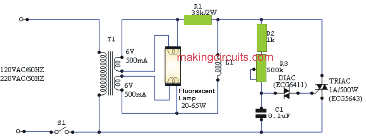
A typical dimmer intended for incandescent lamps cannot be utilized directly to control the luminous strength of fluorescent lamps. Nonetheless, it could be conveniently modified for this specific purpose by adding the modifications pointed out in the figure. In cases like this, the "starter" is removed, while the choke, or the ballast or shock reactance (L1) can certainly continue in the circuit to be able to limit the interference brought on by it. The filaments (cathodes) of the lamp, conversely, are preheated using a transformer by using a couple of independent windings (T1). Consequently, the circuit will not be well suited for slimline or direct start lamps.

The Triac, the diac and its related components (r2, P2 and C1) together bacome a standard phase control dimmer to which any kind of snubber system formerly incorporated into has been eliminated. Potentiometer P1, which usually works as a brightness control, has to be designed with a plastic material shaft. If the control range is inadequate, it is possible to test out some other values ​​of C1. The second option should have a baseline operating voltage of 400V. The resistance R1 (33k / 2W) could be substituted by 3 resistors of 100 k / 0.5W each in parallel.

simple fluorescent tube light lamp dimmer circuit

You'll also like:

  • 1.  5KVA Voltage Stabilizer Circuit
  • 2.  High Current 78XX Regulator Circuit
  • 3.  Light Dimmer Circuit
  • 4.  Incubator Heater Backup Circuit with Charger
  • 5.  How Triacs Work: Explained
  • 6.  Mains AC Surge Protector Circuits

About Admin

Hey friends, Thanks a bunch for stopping by this site! I am an engineer with a Bachelor of Engineering in Electronics and Telecommunication. One of my passions is gathering information from all sorts of electronics books and tutorials. I then take that information and compile it into a language that is super easy to understand. My goal is to make those complex electronics circuit concepts and technical terms much more accessible for all the new and budding electronics engineers out there. I can also design customized circuit diagrams as required by the users.
If you have any questions related to this field, please do not hesitate to drop a comment! I am always here and ready to help you out with any queries you might have. I cannot wait to hear from you!

Reader Interactions

Comments

  1. Željko Zdjelarević says

    April 7, 2025 at 1:29 pm

    This scheme doesn’t work for you, you’re missing one wire.

    Reply
    • Admin says

      April 14, 2025 at 1:20 pm

      Which wire is it missing?

      Reply

Leave a Reply Cancel reply

Your email address will not be published. Required fields are marked *

Primary Sidebar

Categories

  • 3 Phase (4)
  • 8051 Microcontroller (1)
  • Arduino (11)
  • Audio and Amplifier (102)
  • Automation (8)
  • Battery Chargers (64)
  • Bicycle Projects (4)
  • Car and Motorcycle Projects (39)
  • Datasheets (10)
  • DIY Projects (5)
  • Electrical (15)
  • Free Energy (6)
  • Games Projects (2)
  • High Voltage (14)
  • Hobby Projects (30)
  • Household Circuits (2)
  • IC 555 Circuits (5)
  • Ignition Circuits (2)
  • Indicators (50)
  • Infrared (6)
  • Inverter Circuits (29)
  • Lights and Lamps (97)
  • Medical (8)
  • Meter and Tester Circuits (38)
  • Motor Driver (17)
  • New Circuits (56)
  • Oscillators (30)
  • Pets and Pests (5)
  • Power supply (80)
  • Protection Circuits (25)
  • PWM (9)
  • Remote Control (20)
  • Security and Alarm Circuit (48)
  • Sensors and Detectors (66)
  • Signal Processor (23)
  • Solar Controller Circuits (62)
  • SSR (3)
  • Temperature Controller (20)
  • Timer (25)
  • Transformerless (7)
  • Transmitters (12)
  • Tutorials (45)
  • UPS (2)
  • Voltage Regulators (57)
  • Water Sensor and Controller (29)
  • Home
  • Privacy Policy
  • Contact
  • Disclaimer
  • Copyright

© 2025 · Making Easy Circuits