The concept of the proposed simple induction heater circuit is straightforward. The coil generates high-frequency magnetic flux and then metal things in the the coil produces eddy currents which can be found warming it.
The hysteresis drawdowns additionally help cause the heating. Possibly even for an undersized coil such as this a current around 100A is commonly employed, consequently, in suggestive of with the coil you will find a resonant capacitance, which makes up their inductive nature.
Coil-capacitor circuit ought to be powered at their resonant frequency. The motivation current is significantly less than the current throughout the coil. The power source is a straightforward MOSFET Half Bridge regulated by circuit IR2153. The MOSFETs possess a compact heatsink.
Driving frequency is tuned to resonance by potentiometer. The resonance is determined by a neon light bulb. The frequency could be regulated in the area of approximately 20 to 200 kHz.
The control circuit necessitates auxiliary voltage of 12-15Vdc. I will be employing an undersized building wall socket power supply, however simply because just few mA can be used, feel free to use precipitating resistor or capacitor.
Mainly because the output driver might not be associated straight in, you can find a complementing choke in succession. It includes around twenty turns 1.5 mm diameter on a 8x10 mm ferrite core as well as the strength may be established by modifying the air gap.
The induction heating is operated straightly from electrical grid. It will be implementing full-wave rectified voltage with no filtration electrolytic capacitor. A light bulb is attached in series to reduce the current and help save the circuit in error situation, overload or undesirable performance.
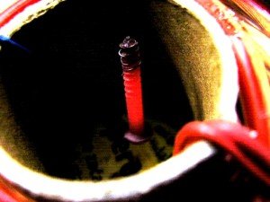
Work coil of induction heating needs to be sturdy copper wire or more desirable a copper tube and possesses approximately 12 - 30 turns on a 3 - 10 cm diameter.
Resonance capacitor is as a result of the large amperage crafted from numerous (at least 6) capacitors. Inside my example, the coil carries 26 turns and capacitors is 6 x 330n 250V~.
Together are getting piping-hot after extended workings. The resonance frequency is approximately 29 kHz. My resonant circuit is built quickly, with a bit of added trial and error it is possible to arrive at significantly better end results.
This really is my very first experience at simple induction heater circuit

In your discussion you say that you used the neon bulb to determine the resonance. In what way do you do that? I would like to see the output waveform if you ever have an opportunity to measure it with an oscilloscope, etc.
Just hold one terminal of the neon lamp with your fingers, and bring the other open terminal of the neon bulb near the LC tank, if the neon glow or flickers will indicate the resonance. Yes, you can use an oscilloscope for measuring this…
can i transform this parallel resonance to series resonance?
You can do but the circuit configuration will change…
could you please tell me4.7 nf and 4.7 ohm resistor are used in parallel with capacitor and coil?
Yes, but before the TL….
i would like to know what is the maximum power of the induction heater
Around 200 watts, but can be increased by upgrading MOSFET and work coil
Instead of irf 840 i would like to use irf260n,which has a drain current of 50 A.using this can i increase the input power.what modification can be made to upgrade this to 1500 watts.
Yes, that looks feasible, but the work coil wire thickness will also need to be upgraded accordingly….
what about the gate resistor and IC,tank capacitor values.
everything is given in the diagram and the article.
what is the L value of your work coil?
L is not required because the number of turns, and diameter is already given.
I wonder if I can insert a pipe into the induction coil. Can I use the heater as a water heater. How long can it works heating?
Yes you can do that. The heater will work as long as it connected to the power supply
Thanks Admin ????
I’m going to make it.
good afternoon what is the value of the diode between pins 1 and 8 and now what is the value of the tank capacitors.
diode can be FR107 or BA159….capacitors are 330nF each
What do you mean by “The control circuit necessitates auxiliary voltage of 12-15Vdc. I will be employing an undersized building wall socket power supply”? you said as far as I can tell, you supplied the IC with around 300V DC, (assuming the mains is 230V AC). and you used 250V~ capacitor
What about TL. nothing written about TL in text
It is a current limiting coil…20 turns of 1 mm copper wire on any ferrite core will work.
Hello. I’m currently trying to make the same project. One short question, is it possible to use electrolytic capacitor for resonance, if no what is the reasoning for that? Also, why are you using many capacitors instead of using one of higher value?
No, electrolytic capacitor cannot be used here….only metallized polyester because electrolytic can start leaking due to high current and high voltage and high frequency…also the capacitor must be strictly non-polar…
one capacitor will heat up and burn
1. whats DT ?? before capacitor bank ??
2. can i change capacitor 0.47uF with 5uf ?
DT refers to a neon bulb.
0.47uF can be replaced with 5uF, because 5uF is 10 times more than 0.47uF
can i have typical values for the limiting inductor
You can try 1 mH. It is just a current limiter coil
En el diagrama electronico el pin 1 del IR2153 deberia estas conectado a los catodos del puente rectificador??,ademas es posible agregarle una limitación de corriente??
dear sir, why cant an induction emf road way developed ?
How, please elaborate??
Hi dear friend. I want to use this circuit to heat water as an electric water heater. Is it possible to do this? Shouldn’t the pin # 1 IC be connected to the power supply?
Hi Hamed, yes pin#1 should be connected to the positive line, please do it in your circuit, sorry for the mistake.
Hi dear friend. I want to use this circuit to heat water as an electric water heater. Is it possible to do this? Shouldn’t the # 5 IC be connected to the power supply?
Dear friends I am working industrial induction heating in plastic extrusion industry.
I want freelance professionals to design and test induction heaters from 1000w to 50kw
Please contact me at envirable@gmail.com we are equal ownership company
Hi,
How much output power it can generate? can I enlarge it in terms of power so that I could reach up to say 500C in less than a minute? and if so, then what alterations I need to do with the circuit.
and my last question: is it safe to touch the circuit components when it is ON.
azeem.imtiaz@gmail.com
500 degrees in a minute is easily possible, you will have to enhance the coil and capacitor so that it can handle higher current may be upto 50 amps and also upgrade the input power to this level
i have pot having 220 mm dia and 130 mm height.It is magnetic.can this pot achieve 500 deg in a minute with full of water in it?
I don’t think that may be possible with water inside.
could you please elaborate enhancing of coil and capacitor.
You will need to increase the coil wire thickness and test the results with trial and error.
I would like to make an induction heater for an school project, can someone of this blog healp me with diagrams.
Thanks for everything
This is my e-mail eavi931223@gmail.com
Ivan, the idea is already presented in the above article, you can use the same and scale down the parameters for making a smaller variant
Hello. I want to ask you if the project will operate if I powred the circuit with a 12V baytery instead of AC and rectifier. Of cource I am tallking about a low power output here.
I make this question because I observed that there is no large capacitor after the rectifier. So, I assumed that the input power it is not fully rectifiered
hello, i think there’s a typo in the diagram, the 100uF associated with pin#1 of the IC must be connected to the positive rail.
By the way a 12V battery would yield better results than an AC rectified supply
I want tube amplifier circuit
tubes have become obsolete today….
my dear sir or lady Is it possible to explain to me how this circuit works and how current flows from beginning to end and the changes that occur
With greetings and my thanks
Samir Fathy
Samir, the circuit is basically a half wave bridge inverter circuit, which causes induction in the work coil by alternately energizing the LC tank at the set resonant frequency, which ultimately causes the iron load inside the coil to heat up.
the series inductor is used for limiting excess current from entering the work coil
Hello excelent, I have a question
What is DT in the schematic?
thank you, that’s a neon bulb, you can remove it if you want!