• Skip to main content
  • Skip to primary sidebar

Making Easy Circuits

Learn and build electronic circuits

You are here: Home / Sensors and Detectors / Simple Infrared Thermopile Sensor Circuit Explained

Simple Infrared Thermopile Sensor Circuit Explained

Last Updated on January 10, 2018 by Admin Leave a Comment

A simple infrared thermopile sensor circuit diagram is shown underneath. The op amp must be a excellent low-noise unit.

We usually make use of the LTC1050 for such purposes, however various other pin-compatible selections may be present and tried.

(The all-pervasive 741 op amp is not going to be eligible as a "low-noise" substitute, although it is pin-compatible.)

Since this is undoubtedly a low-power circuit, A 78L05, 5V regulator inside a TO-092 casing may be the suitable preference.

The pins on the thermopile sensor A2TPMI are vulnerable, and yes it may very well be a smart idea to connect a minimum of one of the unused pins to an isolated solder pad for mechanical steadiness.

Just about all parts in the diagram are as looked at from "top," meaning through the component angle of a PCB.

Determined by how this simple infrared thermopile sensor circuit is encased to safeguard it from weather condition, it may be recommended to flip the A2TPMI over and attach this within the reverse section of the PCB. If you carry out this, ensure you hook up the relevant pinouts accordingly!
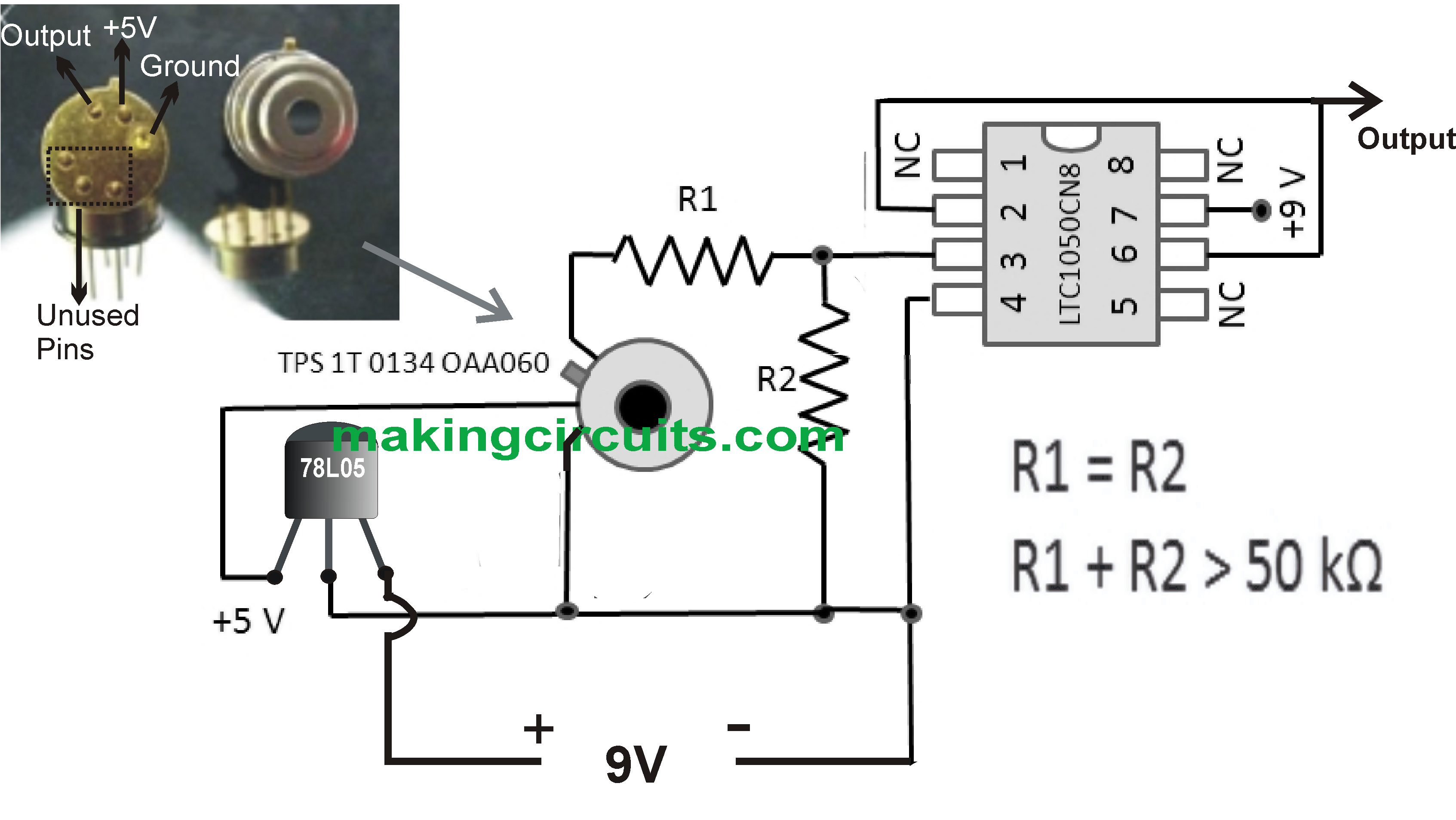
Simple Infrared Thermopile Sensor Circuit Explained

You'll also like:

  • 1.  Touch Operated Flip Flop Relay Switch
  • 2.  Liquid Level Sensor Circuit
  • 3.  How to Make a Heart Rate Sensor with Processor Circuit
  • 4.  Carbon Gauge Circuit
  • 5.  Magnetic Proximity Switch Circuit
  • 6.  Automotive Engine Temperature Controller Circuit

About Admin

Hey friends, Thanks a bunch for stopping by this site! I am an engineer with a Bachelor of Engineering in Electronics and Telecommunication. One of my passions is gathering information from all sorts of electronics books and tutorials. I then take that information and compile it into a language that is super easy to understand. My goal is to make those complex electronics circuit concepts and technical terms much more accessible for all the new and budding electronics engineers out there. I can also design customized circuit diagrams as required by the users.
If you have any questions related to this field, please do not hesitate to drop a comment! I am always here and ready to help you out with any queries you might have. I cannot wait to hear from you!

Reader Interactions

Leave a Reply Cancel reply

Your email address will not be published. Required fields are marked *

Primary Sidebar

Categories

  • 3 Phase (4)
  • 8051 Microcontroller (1)
  • Arduino (11)
  • Audio and Amplifier (102)
  • Automation (8)
  • Battery Chargers (64)
  • Bicycle Projects (4)
  • Car and Motorcycle Projects (39)
  • Datasheets (10)
  • DIY Projects (5)
  • Electrical (15)
  • Free Energy (6)
  • Games Projects (2)
  • High Voltage (14)
  • Hobby Projects (30)
  • Household Circuits (2)
  • IC 555 Circuits (5)
  • Ignition Circuits (2)
  • Indicators (50)
  • Infrared (6)
  • Inverter Circuits (29)
  • Lights and Lamps (97)
  • Medical (8)
  • Meter and Tester Circuits (38)
  • Motor Driver (17)
  • New Circuits (56)
  • Oscillators (30)
  • Pets and Pests (5)
  • Power supply (80)
  • Protection Circuits (25)
  • PWM (9)
  • Remote Control (20)
  • Security and Alarm Circuit (48)
  • Sensors and Detectors (66)
  • Signal Processor (23)
  • Solar Controller Circuits (62)
  • SSR (3)
  • Temperature Controller (20)
  • Timer (25)
  • Transformerless (7)
  • Transmitters (12)
  • Tutorials (45)
  • UPS (2)
  • Voltage Regulators (57)
  • Water Sensor and Controller (29)
  • Home
  • Privacy Policy
  • Contact
  • Disclaimer
  • Copyright

© 2025 · Making Easy Circuits